
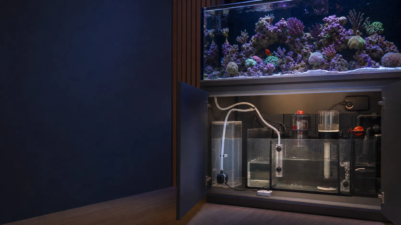

 Published sources
 Product details checked
Switch the auto top-off (ATO) off from a dry, safe control point and disconnect its pump power. If freshwater keeps entering after the pump stops, investigate a siphon. If water enters only while the pump runs, check the sensor reading, pump command and the controller’s documented dosing behavior. A rising sump level with no water coming from the ATO hose can instead be drain-back from the display.
The quickest way to find the cause is to separate the water path from the control path:
- Stop the ATO and mark the waterline.
- Check whether the pump is still being commanded to run.
- If the pump is off but water keeps coming from the hose, test for a siphon.
- Only then clean and reposition the sensor, inspect the pump, and test the controller.
This guide covers reef and freshwater systems, including all-in-one aquariums with rear filtration chambers. The Red Sea ReefATO+ level sensor is intended for seawater systems; its leak detector’s ability to detect RO water does not make the ATO suitable for freshwater aquariums.
Jump to the siphon test, sensor checks, model-specific protection, or reservoir capacity.
First: make the system safe
Before touching a wet cabinet, disable the ATO controller and unplug the ATO pump from the dry side. If water has reached power strips, connectors, or the underside of a cabinet, switch off the affected circuit at the breaker before handling equipment. Keep hands dry and do not reach into the sump while energized equipment is exposed to water.
If the display or sump is already too high, remove water with a clean container or siphon until the normal operating line is restored. Keep replacement water separate from the aquarium until you know whether the system needs freshwater for evaporation or whether a water-change mistake has altered salinity.
In a marine aquarium, measure salinity as well as water level. Removing excess, already mixed aquarium water lowers the level but does not reverse freshwater dilution. Record the salinity and approximate amount added before planning a correction with prepared saltwater. Red Sea’s salt-mixing instructions prohibit mixing dry salt in an aquarium containing animals.
Also check whether saltwater is leaving through a leak or an overflowing protein skimmer. An ATO can correctly detect a falling level while replacing lost saltwater with freshwater. Stop the loss before restoring automatic top-off.
Do not leave a suspected ATO running unattended while you troubleshoot. A controller with a stuck relay, a pump with an external override, or a siphon can defeat an otherwise clean sensor.
A visual diagnostic flow
Use the observed behavior—not the product name—to choose the first branch.
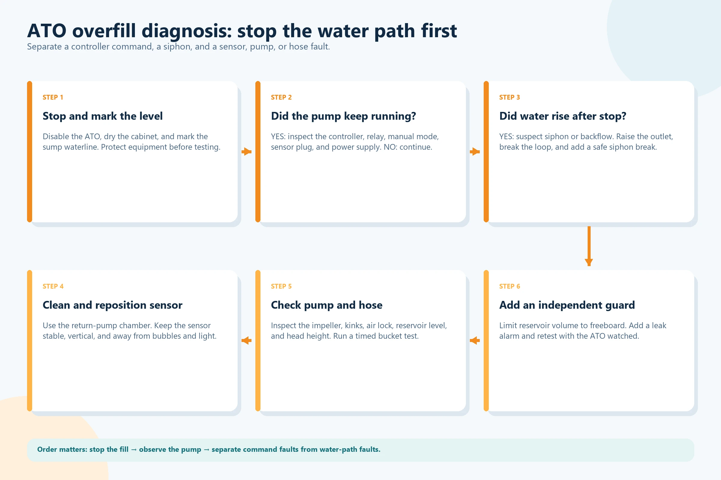
Overfill patterns that look alike
| What you observe | Most likely branch | First useful test |
|---|---|---|
| The pump continues after water reaches the working level | False sensor reading, manual command, controller fault, or a model-specific minimum dose | Record the controller status, disconnect pump power, then check the manual |
| The pump stops, but water keeps coming from the ATO outlet | Forward siphon from the reservoir | Repeat a pump-off test with the outlet at its installed height |
| The sump rises while the ATO outlet is dry | Display drain-back after the return pump stops | Check the return-pump state and allow the sump level to settle |
| Repeated fills start while the return chamber falls or fluctuates | Turbulence, poor sensor placement, restricted flow between chambers, or a leak | Check chamber flow and saltwater loss before moving the sensor |
| Overfill begins after maintenance, a water change, or a restart | Sensor or tube moved, operating level changed, or first-fill timing changed | Restore the operating conditions and inspect the mounting and controller status |
The distinction matters. Replacing an optical sensor will not stop a gravity-fed siphon, and adding a leak alarm will not repair a controller that is permanently powering the pump.
Step 1: establish the normal waterline
Turn the ATO off and let the return pump run normally until the water level settles, if the system is safe to operate. Mark the intended ATO fill-stop level in the return-pump chamber. This is the chamber whose level changes with evaporation in most sump systems. In an all-in-one tank, it is usually the rear return chamber; a sump-free aquarium needs a stable position in the aquarium itself.
Then check the following:
- Is the return pump chamber the only chamber whose level falls during evaporation?
- Has a recent water change, filter cleaning, skimmer adjustment, or equipment move changed the operating level?
- Does the skimmer cup start filling rapidly when the sump level rises? Check the protein skimmer’s operating depth and restart sequence before adjusting its foam setting.
- Is the ATO sensor attached at the intended operating height, with room above it for the high-level safety response?
- Is the reservoir filled with the correct water? Evaporation is normally replaced with freshwater or purified water, while saltwater belongs in a planned water change.
The marked line gives you a reference for every later test. Without it, a small sensor shift and a real controller fault can be difficult to distinguish.
Keep the return-pump-off level separate from this operating mark. Water draining back from the display raises the sump level without adding any new water to the system. Do not lower or raise the ATO sensor to chase that temporary level. After filter cleaning, check that water can pass freely into the return chamber; a clogged sock or media basket can lower the local level even when the system has enough water.
Step 2: find out whether the controller is commanding the fill
Before resetting anything, note the controller’s light pattern, alarm and any recent manual command. Then disable automatic filling through its documented control and watch whether the pump stops. A lit power indicator alone does not prove that the pump is running. If the pump continues to run with automatic filling disabled, disconnect power and check for:
- A manual-fill command that is still active.
- A smart plug, power bar, relay, or aquarium controller that is overriding the ATO output.
- A wet or corroded connector that is shorting or behaving intermittently.
- A damaged sensor cable or a connector that is only partly seated.
- A pump that is connected to constant power instead of the ATO-controlled outlet.
If the pump runs only when the controller is enabled, perform a short controlled test into a clean collection container, with the outlet secured at its normal height. Use the manufacturer’s test or manual-pump procedure and keep enough water over the pump intake. Confirm that stopping the command stops the motor, then disconnect power to distinguish motor operation from continued gravity flow. Do not return the hose to the aquarium yet.
On the ReefATO+ controller, holding the manual pump button runs the pump for as long as it is pressed. Release the button before assessing automatic behavior.
An ATO that cannot reliably remove power from its pump should be treated as failed. Do not compensate by lowering the sensor or shortening the run time; those changes can hide the fault while leaving the pump energized.
Step 3: rule out a siphon before cleaning anything
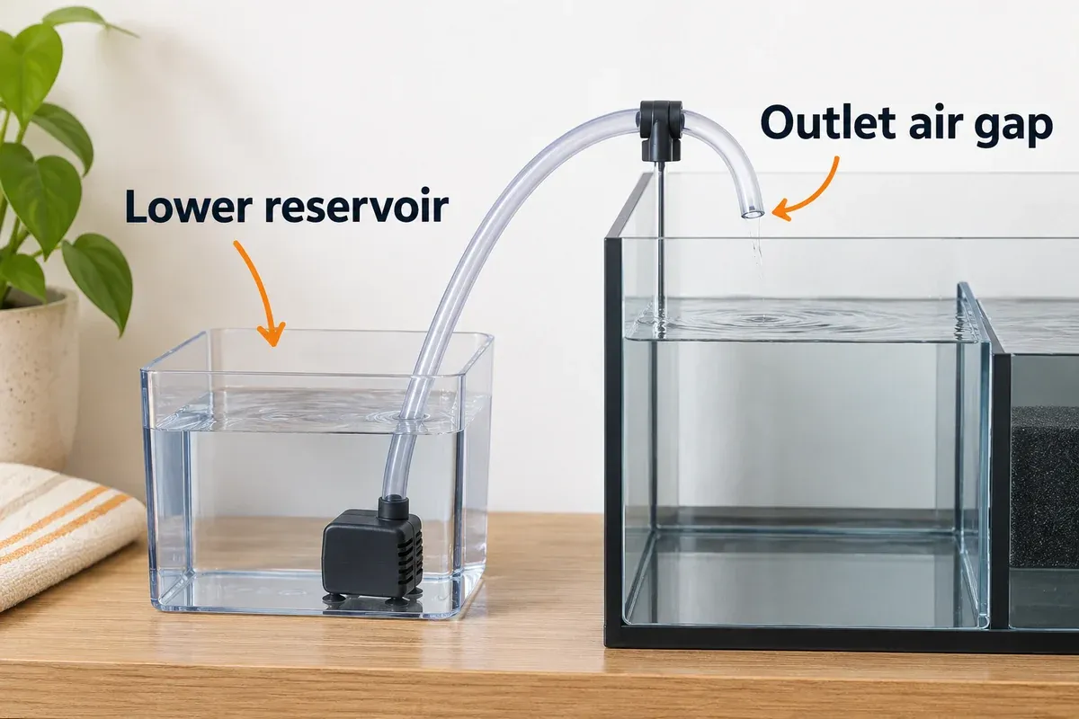
A pump can stop perfectly and the reservoir can still drain by gravity. This happens when the reservoir water surface is higher than the hose outlet and the hose forms a continuous water-filled path. An arch over the cabinet does not prevent this once the line is primed. A submerged outlet can also allow aquarium water to siphon back toward a lower reservoir, so keep an air gap at the aquarium end.
Perform a pump-off test:
- Keep the reservoir in its installed position and secure the hose outlet over a collection container at the same height as the normal outlet. Moving the outlet to a bucket on the floor can create a siphon that did not exist in the aquarium.
- Keep the test volume small, the pump submerged, and the collection container large enough to catch all of it. Keep the power disconnect accessible.
- Run the pump briefly using the model’s permitted procedure until water reaches the outlet.
- Stop the pump and disconnect its power from a dry location.
- Watch the outlet and reservoir level. A few drops of water already in the tube can drain out; sustained flow accompanied by a falling reservoir level identifies a continuing water path.
Route the outlet above the highest expected sump water level, including drain-back when the return pump is off. Secure it so it cannot slide underwater during maintenance. For the Tunze Osmolator 3 installation, the reservoir must also remain below the outlet height. Check this against the fullest reservoir you will use, not just the nearly empty one present during troubleshooting.
The Red Sea ReefATO+ installation diagram places the supplied siphon breaker below the reservoir rim but above its maximum waterline when that waterline can exceed the tube-holder height. Water trickling from this fitting back into the reservoir during pumping is expected. The Duetto² installation diagram also requires its siphon break above the reservoir waterline.
The air opening must stay exposed and drain safely into the reservoir. An outlet above the sump prevents reverse siphoning, but it can still receive a forward siphon from a higher reservoir. Correct both height relationships, or use the siphon-break arrangement specified for the model, then repeat the pump-off test.
Do not drill an arbitrary hole in a dosing tube and assume it is safe. A poorly placed break can spray water into the cabinet, clog with salt or algae, or sit below the reservoir waterline where it cannot break the siphon.
An air gap at the sump and the reservoir height address different siphon risks. The example below shows both height relationships; some models also require their supplied siphon breaker.
Step 4: inspect sensor position and the water around it
Once you know the pump actually stops, inspect the sensor. Use the chamber where evaporation changes the level, with the sensor clear of drain turbulence. The Red Sea installation instructions call for its level probe to be vertical in its holder in the return-pump chamber.
Keep the sensor:
- In the orientation shown in its manual and firmly attached at the intended operating level.
- Away from the drain outlet, return nozzle, powerheads, skimmer bubbles, and moving surface water.
- Within the manufacturer’s water-temperature range, with any protective cover fitted.
- Clear of salt spray, condensation, algae film, and mineral deposits.
- Away from direct light when using optical sensing.
- Positioned so a snail, cable, cleaning magnet, or filter sock cannot move it.
Identify the sensing method before cleaning or adjusting it. The Duetto² has two optical sensors in one fixed housing. The Osmolator 3 combines an optical working sensor with a thermal safety sensor. The ReefATO+ uses titanium electrical-conductivity probes. Do not try to alter the spacing within a combined sensor assembly. Mount the whole assembly so the safety level can be reached without overflowing the chamber.
Clean an optical sensor safely
Switch the controller off before removing the sensor. Wipe an optical sensing surface with a soft cloth and use only the cleaning method approved for that model. Do not scrape the lens with a blade or abrasive pad. The Osmolator 3 maintenance instructions specify soft-cloth cleaning and require the protective cap during operation. Replace a sensor that is cracked or continues giving inconsistent readings after cleaning and correct placement.
The Duetto² placement guidance calls for avoiding microbubbles and direct light. If bubbles stick to the sensing surface, remove the source of bubbles as well as cleaning the sensor. A clean sensor placed beside the skimmer outlet can keep producing the same fault.
For the ReefATO+ titanium probes, remove deposits from the pins using the permitted maintenance method. Return the level sensor to seawater for operation; a freshwater bucket is not a valid substitute for testing its aquarium level sensing.
If the waterline oscillates because the return chamber is turbulent, a clean sensor can still trigger repeated short fills. Stabilize the chamber and reduce turbulence before changing the controller’s delay or sensitivity.
Step 5: test the pump, hose, and head height
An ATO pump is not just an on/off device. Its actual flow depends on the vertical head height, tubing size, bends, fittings, debris, and air in the line. A pump that is too restricted may run for a long time and hit a timeout. A pump that moves more water than the sensor chamber can absorb before the controller reacts can overshoot the line.
Inspect the pump and hose with the pump disconnected:
- The pump should remain submerged to the level specified by its manufacturer and should not run dry.
- Check the impeller chamber for sand, calcium deposits, algae, snail shells, and loose fragments.
- Remove kinks and sharp bends from the tube.
- Confirm that a check valve, siphon breaker, or narrow fitting is not blocked.
- Look for trapped air after a reservoir refill.
- Check that the tube outlet is secure and cannot fall into the sump.
- Confirm that the pump can reach the required height without a long, restricted run.
Measure flow at the installed height
Use the actual tubing, fittings and outlet height for a timed collection test. Keep the pump submerged and use a manual run only if the model permits it. Start timing once water reaches the outlet, collect for a measured short interval, then stop the pump. Record any flow that continues after the motor stops separately from the pumped volume. Red Sea’s actual-flow measurement procedure likewise keeps the outlet at its normal operating height.
Calculate flow in mL/min = collected mL × 60 ÷ elapsed seconds. For an illustrative example, 200 mL collected in 10 seconds is 1,200 mL/min, or 1.2 L/min. At that measured rate, another five seconds delivers 100 mL. These are example values, not measurements of any recommended product. A narrow return chamber can rise noticeably from a small extra volume.
Do not compare that result directly with a pump’s maximum flow rating at minimal head. Maximum delivery height is the limit where useful delivery falls away, not a promise of full flow at that height. Use the model’s approved pump setting and the measured result to decide whether a restriction or excessive flow needs correction.
Do not solve slow filling by installing a much larger pump. The safer fix is to use a pump matched to the ATO controller, tubing, and head height, then verify the controller’s timeout and safety behavior.
Step 6: check controller safety logic and leak protection
After the mechanical checks pass, test the controller’s built-in protection one function at a time. Manufacturer behavior differs, but a well-designed system commonly has some combination of:
- A maximum run-time timeout.
- A second level sensor or thermal safety sensor.
- Detection of a missing, blocked, or dry-running pump.
- A leak sensor that disables top-off.
- An app or local alarm for sensor and overrun conditions.
Know what your model considers a normal fill
| Model | Relevant behavior | What to check before resetting |
|---|---|---|
| Tunze Osmolator 3, 3154 | A 10-second minimum dose can produce a small rise past the optical level. A separate thermal sensor and 10-minute timer provide safety stops. | Distinguish a repeatable small dose from continuing uncontrolled filling. Check flow and available space above the working level. |
| XP Aqua Duetto², DATO-202P | QST alarms when a later refill exceeds six times the first refill’s duration. This timing protection does not cover the first fill. | Check bubbles, reservoir water and tubing. Watch the first fill after a power reset; do not use repeated resets to silence the fault. |
| Red Sea ReefATO+ | Backup level probes, pump-overrun monitoring and enabled leak detection can stop automatic filling. | Read the specific alert, correct its cause and then resume. A manual pump run is a separate command. |
The Duetto² touch button silences its QST alarm without clearing the timing memory; disconnecting and reconnecting power clears that memory. A safety timer limits motor operation. It cannot stop gravity flow through a primed hose, and the water delivered before a timeout may still exceed a small chamber’s capacity.
Use only the manufacturer’s permitted checks, with a small reservoir volume and an accessible dry power switch. Keep an installed seawater level sensor in its normal operating water while collecting pump output separately. Do not deliberately flood the sump to reach the high-level sensor, bypass a safety input, or run the pump dry to create an alarm. If a safety response does not match the manual, stop using the ATO and contact the manufacturer.
Place a separate leak detector on dry surfaces below the most likely failure points:
- On the cabinet floor beneath the reservoir and its hose connections.
- Beneath the sump’s return and drain fittings.
- At the lowest point inside the cabinet.
- Near any hose connection that can spray when the pump starts.
A leak alarm is valuable, but know which kind you have. An alert-only sensor reports water after it reaches its probes. An integrated ATO leak input may also disable the ATO. The GoveeLife Water Leak Detector 1s is an independent alert layer; it does not directly remove power from an aquarium ATO pump. The ReefATO+ combines leak detection with ATO shutdown, but it is designed for seawater systems.
Step 7: make the reservoir part of the safety design
The reservoir limits how much water a failure can add, provided it is not connected to an unlimited refill supply. Size the stored volume around the aquarium’s freeboard, meaning the empty capacity available before water spills. Include the space needed for display drain-back when the return pump stops.
With the ATO disabled, establish the settled return-pump-off level under supervision, only if a shutdown is safe for the aquarium and there is enough room for drain-back. The capacity still available above that level is the starting point for the reservoir limit. Do not count water space trapped behind baffles that will not fill before another chamber overflows.
For a simple rectangular usable area, remaining liters = length in cm × width in cm × spare height in cm ÷ 1,000. In an illustrative unobstructed area measuring 40 × 30 cm, 5 cm of remaining height holds 6 L, about 1.59 US gallons. A full 19 L reservoir exceeds that capacity. Subtract equipment displacement and leave additional margin; do not treat the calculated rim volume as a fill target.
Flood capacity and salinity tolerance are separate limits. A freshwater dose can dilute a reef tank even when the sump has room to contain it. Use the smaller practical stored volume that suits the system, maintain the independent shutdowns, and refill it more often when necessary.
Use a stable opaque container where practical, keep it lower than the hose outlet when the manufacturer allows, and route the cable and tubing so maintenance cannot pull the outlet underwater. Leave room to open the lid without knocking the pump or moving the hose.
The Simplicity 5 Gallon Easy-Fill ATO Reservoir specifications list a 5-gallon / 19-liter capacity, opaque sides, a clear front with volume graduations, a wide fill lid, and 20 inches of required clearance. Mark a lower maximum fill line if your system cannot safely accept the full stored volume.
Products matched to the fault
The products below cover different failure modes rather than competing for one universal “best” label. Verify the exact model, mounting thickness, fittings, reservoir clearance, and saltwater compatibility before installation.
Products matched to the fault
-
Tunze Osmolator 3 Automatic Water Level Controller
Tunze
A plug-and-play aquarium water-level controller with an optical control sensor, independent thermal safety sensor, included dosing pump, tube, and low-voltage power supply. The reservoir is separate.
- 0.5 mm optical level-sensing accuracy stated by Tunze
- Independent thermal safety sensor stops the included pump if the primary sensor does not switch off
- Included Turbelle High Jet 5030 pump with dry-run and blockage protection
- Best for
- Premium ATO with an independent overfill safety sensor
- Safety / fit check
- Independent thermal sensor plus 10-minute safety timer
-
XP Aqua Duetto² Dual-Sensor Aquarium ATO
XP Aqua
A compact dual-optical ATO whose lower sensor handles normal top-off and upper sensor plus QST programming provides a second overfill limit.
- Two optical sensors in one compact mounting assembly
- Secondary sensor and QST programming add overfill protection
- 74 GPH / 280 LPH pump with 8.2 ft / 2.5 m maximum head
- Best for
- Compact ATO with two optical sensors and plug-and-play setup
- Safety / fit check
- Secondary optical sensor; QST timing excludes the first fill
-
Red Sea ReefATO+ 3-in-1 Auto Top-Off System
Red Sea
A reef-specific ATO with titanium level probes, an integrated temperature monitor, a separate leak detector, pump timeout logic, and ReefBeat notifications.
- 3 mm / 1/8 in pump-on to pump-off level band with backup pump-off probes 2.5 cm / 1 in above
- Leak detection disables ATO fill and can trigger an audible alarm and mobile notification
- Pump monitor shuts down on missing pump, overrun, dry reservoir, blocked pump, or missing sensor
- Best for
- Saltwater reef systems that need ATO, leak shutdown, temperature monitoring, and app alerts
- Safety / fit check
- Backup pump-off probes, timeout, dry/blocked-pump logic, leak shutdown
-
GoveeLife Smart Water Leak Detector 1s, 3-Pack
GoveeLife
A standalone alert layer for the floor under the sump, reservoir, or hose fittings, with gateway-based app notifications and a loud local alarm.
- Dual-probe water detection with adjustable alarm up to 105 dB
- IP67 sensor design and up to five-year stated battery life
- Gateway-based app, email, and other alerts with 2.4 GHz Wi-Fi gateway
- Best for
- Independent floor and cabinet leak alerts alongside an ATO
- Safety / fit check
- Local alarm and gateway notifications; alert-only
-
Simplicity 5 Gallon Easy-Fill ATO Reservoir
Simplicity
A 5-gallon / 19-liter ATO reservoir with opaque sides, clear front graduations, pump/tube cutouts, and a wide fill lid designed for cabinet use.
- 5-gallon / 19-liter capacity with clear front graduations
- Opaque black sides help limit light exposure and nuisance algae
- Wide-mouth lid with splash guard makes cabinet refills easier
- Best for
- A dedicated, light-shielded reservoir with an easy-fill lid and visible volume markings
- Safety / fit check
- Limit stored volume to the reserve after drain-back; reservoir has no shutoff
Check the exact model, included fittings, sensor limits, reservoir clearance, and controller instructions before installation.
Tunze Osmolator 3: optical control with thermal backup
The Tunze Osmolator 3 product page specifies an optical control sensor with 0.5 mm stated accuracy, an independent thermal safety sensor and a supplied low-voltage pump. The pump has a 3 m maximum head at its factory setting and 6.2 m in its higher performance setting. Allow for the minimum dose and measured flow when using it in a narrow chamber.
This is a strong fit when you want a dedicated ATO with a separate high-level safety input and you are prepared to supply a reservoir that is sized safely. The included pump and controller reduce the number of parts that must be matched.
The important limitation is conceptual: the safety sensor can stop a commanded pump run, but it cannot stop a gravity siphon that continues through a badly routed hose. The reservoir is separate, and the sensor holder and tube holder have their own mounting limits.
Check current price on Amazon →XP Aqua Duetto²: compact dual optical sensing
The XP Aqua Duetto² product page describes a lower optical sensor for normal top-off, a secondary optical sensor with QST overfill protection, and a compact plug-and-play design. XP Aqua lists a 74 GPH / 280 LPH pump, an 8.2-foot / 2.5-meter maximum head, and a maximum mounting thickness of 1/2 inch / 12.7 mm.
Choose this kind of layout when cabinet space is limited but you still want separate normal-level and high-level sensing. XP Aqua specifically warns against placing the sensor where microbubbles or direct light can interfere with the reading, so a turbulent return chamber still needs to be corrected.
It does not replace a floor leak detector, and its dual-sensor protection does not make a submerged outlet or a siphon-safe hose route optional.
Check current price on Amazon →Red Sea ReefATO+: integrated reef automation and leak shutdown
The Red Sea ReefATO+ product page combines ATO, temperature monitoring, and leak detection. Red Sea specifies a 3 mm / 1/8-inch pump-on to pump-off band, backup pump-off probes 2.5 cm / 1 inch above the normal pump-off level, app notifications, and automatic shutdown for several pump, sensor, and leak conditions.
This fits a saltwater reef cabinet where integrated leak shutdown and app notifications are useful. The manufacturer lists a maximum pump flow of 300 L/h, approximately 79 US GPH, and a maximum head of 2.5 m. Actual flow at the installed height is lower and depends on the tubing and pump setting.
The manufacturer specifies the ReefATO+ for seawater aquariums only. Install the leak detector at a low point, keep the controller dry, and route the outlet according to the manual’s siphon-break instructions.
Check current price on Amazon →GoveeLife Water Leak Detector 1s: independent alert layer
The GoveeLife Water Leak Detector 1s is useful when the ATO itself has no leak input or when you want a second alert path. GoveeLife lists dual probes, a local alarm up to 105 dB, IP67 sensor protection, a gateway-based 2.4 GHz Wi-Fi connection, and app or email notifications.
Place the sensors under the reservoir, sump fittings, and cabinet floor as separate zones. Treat this product as an alert system: it tells you that water reached the probes, but it does not directly cut power to the ATO pump. It therefore complements, rather than replaces, a correctly functioning controller timeout and a siphon-safe hose route.
Check current price on Amazon →Simplicity 5 Gallon Easy-Fill ATO Reservoir: controlled storage
The Simplicity reservoir specifications describe a dedicated 5-gallon / 19-liter container with opaque black sides, clear front graduations, a wide fill lid, tubing and power-cord cutouts, and a maximum listed return-tube diameter of 0.5 inch.
Its practical value is predictable storage and easier refilling. Measure the cabinet, account for the 20-inch required clearance, and keep the stored volume within your system’s reserve after drain-back. If that requires less than five gallons, mark a lower fill line or use a smaller reservoir. Maintain independent shutdown protection as well.
Check current price on Amazon →Repair or replace?
| Finding | Repair first | Replace or escalate |
|---|---|---|
| Sustained flow after pump power is removed | Correct outlet and reservoir heights; install or clear the specified siphon break | Replace damaged tubing or fittings if the water path cannot be made reliably siphon-safe |
| Sensor is dirty or slightly displaced | Clean it, restore the holder, and retest at the marked waterline | Replace cracked or intermittent sensors |
| Pump is noisy, restricted, or air-locked | Clean the impeller, remove kinks, prime the line, and retest in a bucket | Replace a worn pump or use the manufacturer-matched replacement |
| Pump remains powered when the ATO is disabled | Check manual mode, smart plugs, relays, and cable seating | Stop using the controller if it cannot remove pump power |
| An integrated leak sensor alarms but the ATO keeps pumping | Check whether leak shutdown is enabled and follow its documented test | Stop using the ATO if its documented shutdown fails; an alert-only detector has no pump cutoff |
| Reservoir volume exceeds reserve after drain-back | Reduce the stored volume and improve the hose route | Choose a smaller reservoir and retain a tested independent cutoff |
Do not keep resetting a controller that has already overfilled the tank. Repeated resets can mask an intermittent relay, connector, or sensor fault.
Before resuming unattended top-off, observe complete fill-and-stop cycles at the normal outlet height. The motor should stop as its manual describes, gravity flow should cease, and the sensor holder and tube must stay in place. Recheck after a reservoir refill and the next maintenance restart. Note the waterline, light or alarm pattern, collected flow and hose heights so an intermittent fault can be reported accurately.
Common ATO questions
Why does my ATO overfill even though the optical sensor looks clean?
The sensor may be mounted in bubbles or turbulence, sitting at the wrong height, receiving direct light, or connected to a controller that is not interpreting its signal. Check the pump command first, then test the sensor in a stable return chamber and inspect the cable and connector.
Can a siphon fill the aquarium after the ATO pump stops?
Yes. If the reservoir water surface is higher than the hose outlet and the hose remains full, gravity can continue the flow. Keep the outlet above the highest sump level and, where required, above the full reservoir waterline. Test at the installed outlet height; a floor-level bucket changes the height relationship.
Are dual optical sensors enough to prevent an overfill?
They reduce the risk of a single sensor failure, but they do not fix a siphon, an energized relay, an oversized reservoir, or a hose that falls into the sump. They are one layer in a complete water-path and control-path design.
Should I use saltwater in the ATO reservoir?
For normal evaporation replacement, use the water type specified by your aquarium process—typically freshwater or purified water—because salt does not evaporate with the water. Follow the ATO manufacturer’s compatibility instructions, especially for reef-specific products such as the Red Sea ReefATO+.
What is the safest way to test an ATO?
Collect pump output outside the aquarium at the normal outlet height, using the model’s permitted test procedure and a small reservoir volume. Keep the pump submerged, stop its command, disconnect power and watch for sustained gravity flow. Keep a ReefATO+ level sensor in seawater while collecting output separately. Test leak shutdown only as its manual directs.
Why does an ATO overfill after a power outage?
First check whether freshwater is actually entering: display drain-back alone raises the sump when the return pump stops. When circulation resumes, let levels settle before enabling the ATO. A restart can also reset learned refill timing or reveal a moved sensor or hose. Use the model-specific guidance above and monitor the first fill.
Restore automatic top-off only after the fault is resolved
Keep stable sensor placement, a working high-level stop or timeout, correct hose heights, a limited reservoir and leak protection in place together. After a water change, restore circulation and confirm the marked operating level before restarting top-off. The ReefATO+ return-delay setting can delay automatic filling after a configured maintenance action so water levels have time to settle.
Sources and Manufacturer References
- Tunze Osmolator 3 product information
- Tunze Osmolator 3 instruction manual (PDF)
- XP Aqua Duetto² official product page
- XP Aqua Duetto² instruction manual (PDF)
- Red Sea ReefATO+ product page
- Red Sea ReefATO+ instruction manual (PDF)
- Red Sea ReefATO+ English manual: controller, operation and maintenance (PDF)
- Red Sea Salt mixing instructions (PDF)
- GoveeLife Smart Water Leak Detector 1s
- Simplicity 5 Gallon Easy-Fill ATO Reservoir manufacturer specifications