
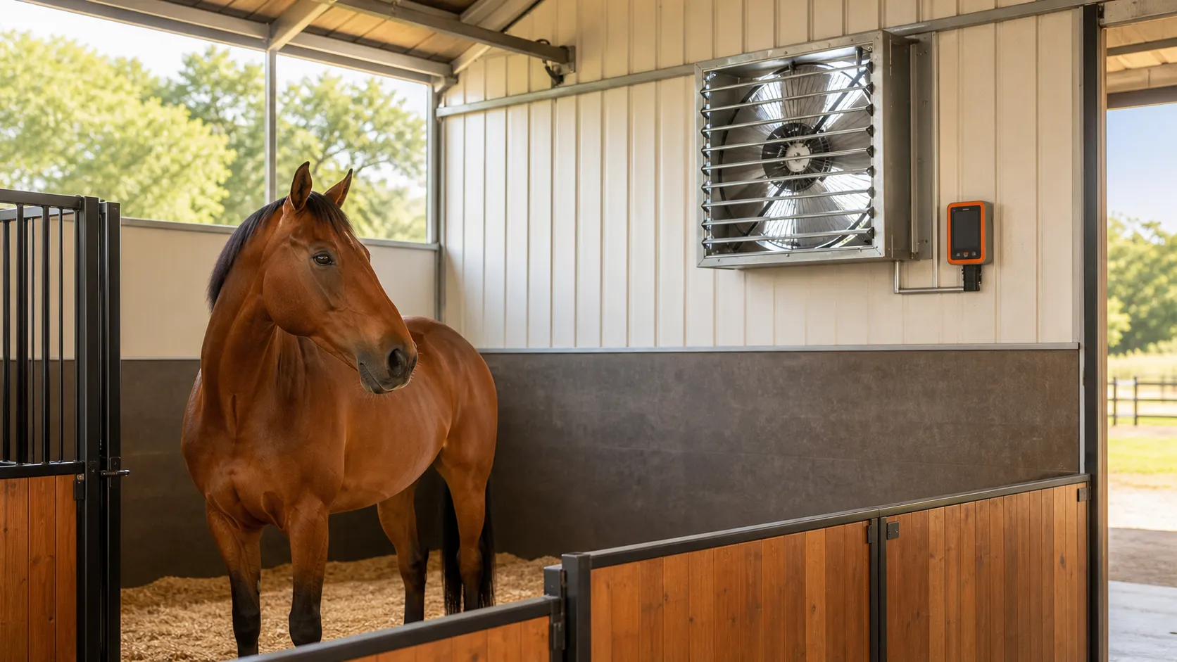

 Published sources
 Product details checked
Start with the combined weight of the horses housed together and the season. For four 1,000-pound horses, the mechanical ventilation targets used here are 100 CFM in cold weather, 500 CFM in mild weather, and 1,300 CFM in hot weather. CFM means cubic feet of air moved per minute.
Those figures tell you how much fresh-air exchange to plan. The fan must deliver that airflow against the resistance of the actual installation, and the incoming air must reach the stalls. A large fan beside an open aisle door can leave a distant stall poorly supplied.
If your barn relies on open sides, doors, eaves, and ridge openings, first assess that natural ventilation system. A fan that blows over a horse can provide a cooling breeze, but its CFM cannot be counted as outdoor air entering the building.
On this page: Calculator and inputs · Seasonal rates · Airflow under pressure · Inlet sizing · Fans and controls · Checks after installation
Calculate your horse barn’s seasonal airflow
Before using the calculator, write down the horses that can occupy the same ventilated space, their current weights, and whether the building will operate with mechanical exhaust or natural ventilation. Use a separate calculation for a genuinely separate air space.
For the fan input, use airflow at the proposed speed and static pressure when that information is available. A free-air figure can help with an initial comparison, but it cannot establish the final fan count.
What to enter and how to read the result
| Input | What belongs in the field | Why it matters |
|---|---|---|
| Number of horses | The horses inside this air space at the same time | This gives the average weight shown in the result; it does not multiply the combined weight again |
| Combined horse weight | The total current body weight, in pounds | This is the animal load used in the seasonal calculation |
| Seasonal design point | Cold, mild, or hot operating conditions | The target changes with the ventilation task |
| Fan airflow to compare | One fan’s CFM at the intended operating point, or a clearly identified free-air value for an initial comparison | Fan count is only as dependable as this input |
| Ventilation mode | Closed mechanical system or open/natural system | An open barn needs an assessment of its openings and airflow, rather than a mechanical fan count |
The calculator rounds the seasonal airflow target upward to the next 50 CFM and rounds the inlet estimate upward to the next 0.1 square foot. It preserves the fan CFM you enter. The combined fan figure is the sum of those inputs, not a measurement of the installed system.
Its inlet estimate uses the combined airflow of the proposed fans. This matters when one large fan substantially exceeds the animal-weight target: the openings must support the airflow you actually intend to run.
The input range covers 1–50 horses, a combined weight of 500–100,000 lb, and fan airflow of 100–100,000 CFM. For a smaller group of miniature horses or an installation outside those limits, use the formula below with the actual weights. Do not increase an input simply to make it fit the tool.
The seasonal CFM rates and their source
The University of Minnesota Extension’s horse-barn ventilation guidance gives these rates for mechanical ventilation:
| Operating condition | Total airflow per 1,000 lb of horse | Total for an assumed 4,000-lb group |
|---|---|---|
| Cold weather | 25 CFM | 100 CFM |
| Mild weather | 125 CFM | 500 CFM |
| Hot weather | 325 CFM | 1,300 CFM |
The progression is cumulative: a continuous 25-CFM minimum, another 100 CFM for mild weather, and another 200 CFM for hot weather. 125 and 325 are already the totals. Adding the three table values would double-count part of the requirement.
These are seasonal planning benchmarks for a building with exhaust fans, controlled inlets, and a predictable air path. They are not minimum air speeds over the horse, a fan diameter chart, or a guarantee that the horse will remain comfortable in every climate.
Penn State’s Horse Stable Ventilation publication describes 25 CFM for cold-weather moisture control, 100 CFM for mild-weather heat removal, and 200–350 CFM for hot weather per 1,000-pound horse. Its wording differs from Minnesota’s staged totals. Use Minnesota’s cumulative rates throughout this calculation.
The calculation
Seasonal airflow target (CFM)
= combined horse weight (lb) ÷ 1,000 × seasonal rate
Assumed example: six horses with a combined current weight of 7,200 lb.
Cold:  7,200 ÷ 1,000 × 25  =   180 CFM
Mild:  7,200 ÷ 1,000 × 125 =   900 CFM
Hot:   7,200 ÷ 1,000 × 325 = 2,340 CFM
The calculator displays rounded planning targets of 200, 900, and 2,350 CFM for these inputs. The underlying seasonal rates remain the same.
If your weights or airflow figures are metric
Convert the combined weight before entering it:
Pounds = kilograms × 2.20462
Cubic metres per hour = CFM × 1.69901
Square metres = square feet × 0.092903
For an assumed group weighing 2,000 kg, the combined weight is approximately 4,409 lb. The unrounded hot-weather result is about 1,433 CFM, or 2,435 m³/h. Enter 4,409 lb and the calculator displays a 1,450-CFM planning target.
Keep the airflow unit consistent when comparing equipment. A fan labelled 3,000 m³/h provides approximately 1,766 CFM at its stated test condition, rather than 3,000 CFM.
Use the horses’ current weight and realistic occupancy
A count of occupied stalls gives you a starting list. It does not tell you the total animal weight.
Use a recent livestock-scale weight where available. Otherwise, use an appropriate body-measurement method and record that the result is an estimate. The University of Minnesota’s bodyweight guidance distinguishes current weight from ideal weight and provides breed-specific equations. For ventilation, enter current weight; an ideal-weight estimate describes a different question.
Keep a short record with the horse’s identity, weight, measurement method, and date. A group containing ponies and draft horses needs that individual accounting more than a uniform group does.
Calculate for the busiest normal period when the barn is occupied. If horses usually live outdoors but come inside together during summer afternoons, use that indoor group. If boarding occupancy changes, revisit the total before the next busy season.
| Assumed occupants | Combined weight | Cold target | Mild target | Hot target |
|---|---|---|---|---|
| Two 1,000-lb horses | 2,000 lb | 50 CFM | 250 CFM | 650 CFM |
| Four 900-lb horses | 3,600 lb | 90 CFM | 450 CFM | 1,170 CFM |
| Four 1,300-lb horses | 5,200 lb | 130 CFM | 650 CFM | 1,690 CFM |
| Six horses totalling 7,200 lb | 7,200 lb | 180 CFM | 900 CFM | 2,340 CFM |
| Twelve 1,000-lb horses | 12,000 lb | 300 CFM | 1,500 CFM | 3,900 CFM |
These are calculated examples, not measured barns. The two four-horse groups differ by 520 CFM at the hot-weather rate despite having the same stall count.
Animal weight does not describe every source of heat or moisture
A wash bay, wet bedding, stored hay, a sun-heated roof, or an adjoining indoor arena can change the conditions in the building without changing the number of horses. List these separately when planning the system.
Do not invent extra “horse equivalents” for those loads. A ventilation designer can assess the building and any additional demand. A CFM target derived from horse weight is a useful input to that work, rather than a complete description of the barn.
Decide how fresh air will enter and stale air will leave
A mechanical exhaust system removes air through a fan and draws outdoor air through deliberate inlets. A natural system relies on wind and buoyancy through building openings. A circulation fan moves air already present.
| Barn arrangement | What to assess first | What the calculator can contribute |
|---|---|---|
| Enclosed barn with planned mechanical exhaust | Fan performance, distributed inlets, controls, and leakage paths | A seasonal airflow target and a conditional fan-count estimate |
| Open-sided or naturally ventilated barn | Openings, wind exposure, sheltered stalls, and calm-weather conditions | A reference for animal load, without proving natural air exchange |
| Closed stall with an interior fan | Access to outdoor air and a route for stale air to escape | A reason to address air exchange before relying on a breeze |
| Building that changes between open and closed operation | A clear operating plan for each arrangement | Targets for the mechanical arrangement only |
Penn State explains that air exchange and air distribution are separate requirements. A fan running in the aisle does not establish either requirement inside every stall.
Trace the air path through each stall
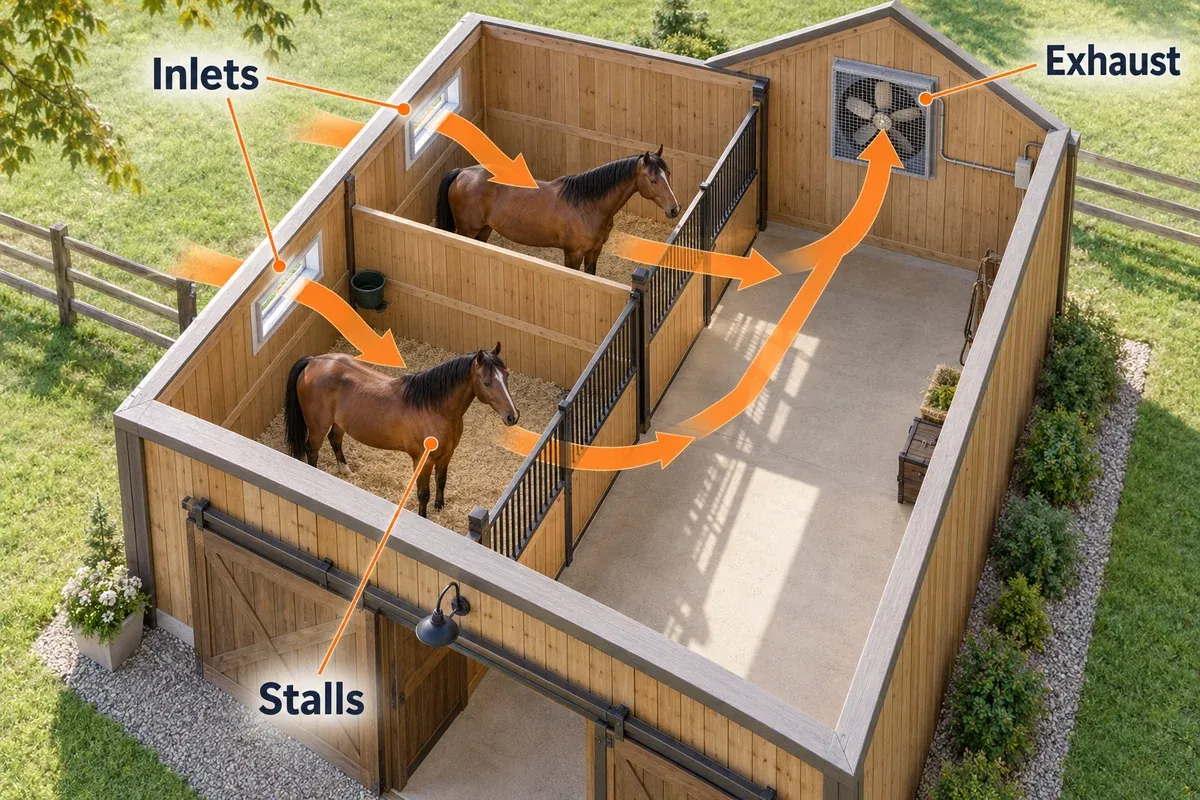
On a simple barn plan, mark outdoor inlets, stall partitions, internal doors, and exhaust outlets. Follow the route:
Outdoor air → distributed inlets → occupied stalls → exhaust fan → outdoorsCheck whether solid partitions interrupt that route. A large opening beside the fan can let incoming air travel straight back outdoors while bypassing the horses. In a divided building, an open aisle can receive most of the airflow while enclosed stalls receive less.
Provide each stall with a usable route to outside air and onward to an outlet. Pay particular attention to corners, enclosed end stalls, and rooms below a hayloft. Increasing motor size will not create a missing connection through a solid wall.
Follow the arrows in the example below, then trace the route through each stall on your own plan. A blocked partition or a shortcut beside the fan changes that route.
Plan for calm days in an open barn
Walk the stalls when there is little wind, as well as on a breezy day. An opening that works well under one wind direction may offer little movement under another.
For the open summer arrangement described by Minnesota Extension, large open doors and windows change the system, and circulation fans can move air over the horses. A purpose-designed tunnel or hybrid system needs its own operating instructions; do not apply a blanket “doors open, fans off” rule to every building.
The natural-mode setting therefore does not give a fan count or mechanically calculated inlet area as a completed design. It directs attention back to the building openings.
Free-air CFM and airflow under pressure
Free-air CFM is measured at zero static pressure. Static pressure is the resistance the fan works against, often expressed in inches of water gauge, abbreviated in. w.g. or in. H₂O.
Inlets, shutters, guards, ducts, and obstructions affect resistance. The fan’s performance table or curve shows how airflow changes as pressure rises. Use the value for the exact model, speed, and test arrangement.
For two of the iLIVING models discussed here, the manufacturer’s performance table, printed page 7, provides these values:
| Exact model | At 0.00 in. w.g. | At 0.125 in. w.g. | At 0.25 in. w.g. |
|---|---|---|---|
| ILG8SF24V | 4,244 CFM | 2,676 CFM | 2,220 CFM |
| ILG8SF36S | 6,128 CFM | 4,380 CFM | 2,620 CFM |
These are manufacturer performance data, not measurements in your barn. The 24-inch model’s airflow at 0.125 in. w.g. is about 37% below its free-air figure. For the 36-inch model, the difference at 0.25 in. w.g. is about 57%.
The table shows why a fixed percentage allowance is unreliable: different models lose different amounts of airflow, and the loss changes with pressure. Nor does a larger blade diameter establish better airflow at every operating point.
How the same fan can give a different fan count
Return to the assumed 7,200-lb group and its 2,340-CFM hot-weather target:
- At the ILG8SF24V’s free-air value of 4,244 CFM, one fan appears sufficient.
- If the actual operating pressure is 0.125 in. w.g., its 2,676-CFM value still exceeds the target.
- If the actual operating pressure is 0.25 in. w.g., its 2,220-CFM value falls below the target.
The calculator’s rounded 2,350-CFM target reaches the same conclusions. Entering 2,220 CFM returns two fans; entering 2,676 CFM returns one.
This is a conditional calculation. Two fans in the same building can change the operating pressure, and both need adequate incoming air. Adding their table values does not replace assessment of the combined system.
What to request before choosing a fan
Ask for the exact model’s airflow-versus-pressure data, the speed used, and the accessories included in the test. Then match that information to the proposed installation.
A statement such as “covers 5,000 square feet” lacks the horse weight, season, building height, airflow distribution, and pressure needed for this calculation. Likewise, a full-speed CFM value does not establish airflow at a lower dial setting.
If suitable performance data are missing, compare a model that provides them or ask the manufacturer for the missing information. Increasing an unknown rating by a guessed safety factor does not make it known.
Size fresh-air inlets for the airflow you will run
Penn State gives an initial inlet-sizing allowance of 1.7 square feet per 1,000 CFM of fan capacity. Use it to estimate usable opening area, then assess inlet placement and operation.
Initial free inlet area (ft²) = operating fan airflow ÷ 1,000 × 1.7For the assumed 2,340-CFM target:
2,340 ÷ 1,000 × 1.7 = 3.978 ft²
Approximately 4.0 ft², or 0.37 m²
However, if you intend to run a fan at 4,244 CFM, calculate around that airflow:
4,244 ÷ 1,000 × 1.7 = 7.2148 ft²
Approximately 7.22 ft², or 0.67 m²
That is why the calculator shows 7.3 ft² for one fan entered at 4,244 CFM. The smaller 4.0-ft² figure belongs to the 2,340-CFM operating target, not to unrestricted full-speed operation of the larger fan.
For two fans entered at 2,220 CFM each, the combined comparison airflow is 4,440 CFM and the tool shows 7.6 ft². The actual inlet design and pressure must be checked with both fans operating.
Free area differs from the outside dimensions of a vent
A vent’s frame, louvers, screen, and backing can reduce its clear passage. Use the vent manufacturer’s free-area figure when available.
Assumed opening example: if a vent provides 60% free area, obtaining 4.0 ft² of free area requires about 6.67 ft² of gross opening. The 60% figure is an example, not a standard allowance for every louver.
A fan’s wall opening is another dimension entirely. The iLIVING manual, printed page 6, specifies a 25-inch-square opening for the ILG8SF24V and a 37-inch-square opening for the ILG8SF36S. Those are mounting dimensions, not fresh-air inlet sizes.
Distribute the openings and keep them usable
One large inlet may satisfy an area calculation yet leave several stalls poorly served. Spread the inlet provision across the occupied space, taking partitions and the exhaust route into account.
Check each stage of operation. Adjustable inlets may need a different opening arrangement when a small winter stage runs than when all summer fans run. Leaving every inlet wide open at low flow can change how air enters and mixes; closing them too far can restrict the fan.
Inspect both sides of each opening. Hay, stored equipment, cobwebs, packed dust, or a later building alteration can obstruct a vent that looked adequate on the original plan.
Choose a seasonal fan arrangement, not only a maximum CFM
For identical fans with verified airflow at the intended operating point:
Fan count = round upward(seasonal target ÷ one fan’s operating CFM)Use the rounded target if you are reproducing the calculator’s result. For fans with different capacities, add the verified airflow of the fans that run together at each stage.
A small barn can need a much smaller winter stage
The assumed two-horse, 2,000-lb example needs 50 CFM in cold weather and 650 CFM in hot weather. A fan rated at several thousand CFM can exceed the summer requirement while offering no demonstrated way to provide the winter minimum.
Variable-speed control helps only when the motor supports it and the resulting airflow is known. A knob marked “low” is not a CFM reading. The shutters also need to open and operate correctly at that setting.
Choose equipment with a suitable low-flow operating point or use a separately sized minimum-ventilation stage. Avoid buying a large single-speed fan solely because it clears the summer calculation.
Staging must account for all fans that run together
For the assumed 7,200-lb group, the unrounded targets progress from 180 to 900 to 2,340 CFM. The additions between stages are 720 CFM and 1,440 CFM.
Those differences help describe the desired operating sequence, but they are not automatic purchase sizes. Available fans, pressure, inlet control, and the minimum stage’s actual delivery determine the final arrangement.
A backup fan only provides useful resilience if its power supply, controls, and air path remain available during the relevant failure. Two fans sharing a failed circuit will both stop.
Fans and controllers to compare after sizing
The two fan examples below have model-specific pressure data. They remain conditional choices for a barn: motor enclosure, permitted environment, wiring, guarding, and the complete air path still need to suit the installation.
Penn State’s equine fire-prevention guidance recommends fans rated for agricultural use with enclosed, sealed motors. General descriptions such as “industrial,” “weather resistant,” or “for barns” do not establish every part of that suitability.
The iLIVING manual restricts these utility fans to general-purpose exhaust and excludes areas containing corrosive or explosive materials. An enclosed motor or UL listing does not override those limits. If your barn environment falls outside the permitted use, choose equipment specifically approved for it.
Two exhaust fans with published pressure data
-
iLIVING ILG8SF24V 24-Inch Variable-Speed Shutter Exhaust Fan
iLIVING
A 24-inch variable-speed shutter fan with an enclosed, thermally protected motor, automatic shutters, and a separate compatible controller.
- 4,244 CFM at zero static pressure; 2,676 CFM at 0.125 in. w.g.
- Variable-speed motor intended for a compatible iLIVING controller
- Enclosed, thermally protected 1/4-HP motor; 2.75 A
- Use case
- Adjustable wall exhaust where verified airflow and the permitted environment match the barn
- Free-air airflow
- 4,244 CFM at 0.00 in. w.g.
- Airflow under pressure
- 2,676 CFM at 0.125 in.; 2,220 CFM at 0.25 in. w.g.
- Control
- Variable-speed motor; compatible controller sold separately
- Electrical specification
- 120 V / 1/4 HP / 2.75 A
-
iLIVING ILG8SF36S 36-Inch Single-Speed Shutter Exhaust Fan
iLIVING
A 36-inch single-speed shutter fan with an enclosed, thermally protected 1/2-HP motor, automatic shutters, and published pressure-dependent airflow.
- 6,128 CFM at zero static pressure; 4,380 CFM at 0.125 in. w.g.
- Single-speed operation with automatic aluminum shutters
- 115 V, 1/2 HP, 6.0 A, and 825 RPM
- Use case
- A separately switched exhaust stage where verified airflow and environmental suitability are confirmed
- Free-air airflow
- 6,128 CFM at 0.00 in. w.g.
- Airflow under pressure
- 4,380 CFM at 0.125 in.; 2,620 CFM at 0.25 in. w.g.
- Control
- Single speed; control gear must be designed for the exact motor
- Electrical specification
- 115 V / 1/2 HP / 6.0 A / 825 RPM
Pressure data are at the manufacturer’s tabulated operating speed. Confirm agricultural suitability, permitted exposure, and airflow at the speed your system will use.
ILG8SF24V: an adjustable fan with a separate control
The iLIVING ILG8SF24V has a completely enclosed, thermally protected motor, automatic shutters, a 1/4-HP rating, and a stated 2.75-amp draw. Its separate compatible controller lets you choose manual speed adjustment or automatic control.
For the assumed six-horse example, it exceeds the hot-weather target at 0.125 in. w.g. but falls below it at 0.25 in. w.g. That comparison is more useful than assigning the model to a fixed number of stalls.
Its main remaining question is the lower seasonal range. Full-speed pressure data do not prove the 180-CFM winter operating point. Establish that lower delivery with suitable documentation or measurement before relying on one fan for every season.
Installation uses a rigid wall frame and approved electrical connections. Follow the exact manual and motor nameplate; a compatible plug-in controller does not eliminate the fan’s wiring requirements.
Check current price on Amazon →ILG8SF36S: a single-speed option for a separately controlled stage
The iLIVING ILG8SF36S has a 1/2-HP enclosed, thermally protected motor, a stated 6-amp draw, and automatic shutters. The manufacturer specifies hardwiring.
For an assumed 12,000-lb group needing 3,900 CFM in hot weather, its 4,380-CFM value at 0.125 in. w.g. exceeds the target. Its 2,620-CFM value at 0.25 in. w.g. does not.
Because this is a single-speed fan, consider it as a stage in a planned system. Its full-capacity operation is a poor match for that group’s 300-CFM winter minimum. The ILG8SFST and ILG8SFRC variable-speed controllers are incompatible with this single-speed model.
Check current price on Amazon →Three models that need additional performance data
The 20-inch ILG8SF20V-ST has a material documentation mismatch. Its product page gives 3,368 CFM. The linked Thermospeed manual, printed page 8, uses an ILG8SF20V-1 row with 3,000 CFM at zero pressure, 1,900 at 0.125 in., and 350 at 0.25 in. Obtain the correct performance row for the supplied fan before sizing from either set. Do not substitute the similarly named ILG8SF20V or ILG8SF20V-T.
The 30-inch ILG8SF30V-T has two speeds, an integrated thermostat, and a stated 5,088-CFM value. Its thermostat-series manual does not provide a pressure-dependent performance table. Obtain delivery data for both speeds and the intended pressure. The pressure row for the ILG8SF30S belongs to a different model.
The VEVOR AMX-FAG36 has an 11,000-CFM headline value and a manufacturer answer excluding a variable-speed dial. That value alone does not establish airflow at operating pressure or agricultural motor suitability. Keep it out of the barn shortlist until those requirements are documented.
Match the controller to the exact motor
Controls for compatible variable-speed iLIVING fans
-
iLIVING ILG8SFST Thermospeed Temperature and Speed Controller
iLIVING
A plug-and-play iLIVING controller with an NTC temperature sensor, automatic on/off cycling, and solid-state full-range speed control.
- Temperature and speed control with automatic on/off cycling
- NTC temperature sensor and solid-state full-range speed control
- 120 V, 3 A FLA, 18 A LRA, and UL listing stated by iLIVING
- Control task
- Automatic temperature cycling and variable-speed control for compatible iLIVING fans from 7 to 24 inches
- Function
- Temperature cycling + full-range variable-speed control
- Electrical limit
- 120 V / 3 A FLA / 18 A LRA
- Compatible equipment
- iLIVING variable-speed shutter fans from 7–24 inches; not single-speed
-
iLIVING ILG8SFRC Smart Remote Thermostat, Humidistat, and Timer Kit
iLIVING
A controller kit with a programmable thermostat, humidistat, timer, dual temperature sensing, and low/medium/high or automatic speed control.
- Automatic cycling by temperature or humidity plus a 24-hour timer
- Receiver and remote with dual temperature sensors
- Solid-state speed control and up to 1,000 feet of control range stated by iLIVING
- Control task
- Programmable temperature, humidity, timer, and remote control on compatible iLIVING variable-speed fans
- Function
- Temperature, humidity, timer, remote, and L/M/H or automatic speed
- Electrical limit
- 120 V / 3 A FLA / 18 A LRA
- Compatible equipment
- Compatible iLIVING variable-speed shutter fans; not single-speed
-
iLIVING ILG8SFSC Solid-State Variable Speed Controller
iLIVING
A rotary solid-state controller with on/off function, a single-gang wall-plate format, and an 8-amp 120-volt rating.
- Rotary speed adjustment with on/off function
- 120 V and 8 A rating stated by iLIVING
- Fits a standard single-gang box and is UL listed
- Control task
- Simple wall-mounted speed adjustment for a compatible iLIVING variable-speed shutter fan
- Function
- Rotary solid-state variable-speed control with on/off
- Electrical limit
- 120 V / 8 A
- Compatible equipment
- See product page
These controls do not measure CFM. Preserve minimum ventilation when automatic temperature, humidity, or timer settings switch another stage off.
The ILG8SFST Thermospeed controller provides temperature cycling and variable-speed adjustment for compatible iLIVING variable-speed shutter fans from 7 to 24 inches. Its rating is 120 V, 3 A full-load current and 18 A locked-rotor current. It excludes single-speed fans.
The ILG8SFRC remote kit adds temperature, humidity, timer functions, and remote sensing. It also has a 3-A full-load rating and excludes single-speed models. A remote sensor helps only if its location represents the occupied stall conditions.
The ILG8SFSC is a manual rotary speed control rated at 120 V and 8 A for compatible speed-controllable motors. It provides no automatic temperature or humidity response.
Match voltage, motor type, full-load and starting requirements, installation method, and permitted exposure. Do not add several fans to one controller simply because their plugs fit. The 30-inch fan’s separate built-in arrangement should not be connected to a smaller controller based on the shared brand name.
Set up a seasonal operating sequence
Minnesota’s staged example uses a continuous cold-weather stage, a mild stage around 50°F, and a further stage around 60°F. These are approximately 10°C and 15.6°C. They are example indoor activation settings, not veterinary heat-stress thresholds or universal thermostat instructions.
Cold weather
Keep the planned minimum exchange available. A temperature controller that switches the only fan off on a cold night can remove that provision precisely when doors are closed.
Look for condensation and persistent dampness, and examine the inlet route before reducing ventilation to preserve warmth. Keep bedding dry and protect vulnerable horses through an appropriate care plan. Closing all fresh-air openings changes the air supply for every occupant.
Mild weather
Confirm that the next stage adds enough airflow to reach the mild total. Check the sensor location, the opening of the shutters, and the inlet response when that stage starts.
If a stage repeatedly cycles while a distant stall remains still, inspect distribution and sensing. A thermostat near a warm roof can respond to conditions different from those around the horse.
Hot weather
Confirm that the maximum planned arrangement delivers its target with the intended doors, inlets, and controls in their operating positions. Repeat the stall checks on a calm, hot day.
When changing to an open natural arrangement, follow the plan for that system. Keep shade, accessible water, and direct observation of the horses in place regardless of the fan setting.
Installation checks before the horses use the space
Use an installer who understands the equipment and barn environment. The iLIVING installation manual calls for qualified electrical work, secure mounting, grounding, and isolation before service.
- Environment: Obtain confirmation that the fan, motor, controls, and connections suit agricultural dust, moisture, corrosion exposure, and the proposed location. Follow any prohibited-use conditions.
- Mounting: Frame the prescribed opening rigidly. A flexing frame can affect the propeller and shutters. Keep the discharge side clear and accessible for inspection.
- Guarding: Keep horses, handlers, and stored equipment away from moving parts. A high mounting position does not by itself establish adequate protection.
- Power: Match the motor nameplate and control ratings to the circuit. Protect cables from chewing, trampling, sharp edges, and wet cleaning.
- Weather exposure: Assess wind-driven rain, exterior shutters, and drainage. A weather-resistant blade or shutter does not make every electrical part suitable for outdoor exposure.
- Service access: Leave safe access for cleaning and replacement. Reaching over a horse or using improvised supports is a poor maintenance arrangement.
- Operation: Document which fan runs continuously, what starts each additional stage, and what to do after a fault or power interruption.
Penn State’s fire-prevention guidance also calls for removing dust and cobwebs, checking cords, and keeping electrical equipment away from combustible material. A controller’s off button is not sufficient isolation for work on a fan.
Check the installed system at every operating stage
Turning blades and moving shutters establish that a fan operates. They do not establish the required CFM or fresh-air distribution.
Keep a record of the fan model, active stage, speed setting, inlet position, door position, occupancy, and weather. Without those conditions, two airflow checks may describe different systems.
1. Check the openings
Confirm that each active fan’s shutters open fully and that intake and discharge paths are clear. Look for rubbing blades, loose guards, vibration, or a shutter that sticks.
Check the fresh-air inlets with the winter stage and again with the summer combination. An opening must function at the airflow actually being used.
2. Check the stalls
Compare the aisle, end stalls, and enclosed corners. Observe conditions where the horse breathes, including its lower head position when feeding. Keep hands and any inspection material away from operating blades.
Check whether fresh air can enter the stall and leave it. A stall door being open during your inspection can hide a problem that appears when the door is normally closed.
3. Check measured delivery when capacity matters
Have a ventilation professional measure static pressure and airflow with appropriate instruments and a method suited to the fan arrangement. Compare the measured operating point with the correct manufacturer data.
A single airspeed reading in front of a fan cannot be converted into dependable CFM without a representative velocity measurement and the relevant area. Feeling a breeze is also not a capacity measurement.
Ask for the result in CFM or m³/h, with fan speed and building-opening positions recorded. Verify the minimum stage as well as the hot-weather stage.
4. Recheck under normal occupancy
Inspect the barn when the expected horses are inside and the usual bedding, doors, and feeding arrangements are in use. A satisfactory check in an empty building does not describe every occupied condition.
Persistent condensation, strong odors, or still, warm stalls warrant investigation even when the fan’s measured total appears sufficient. They help identify a problem; their absence is not proof that every air contaminant is at an acceptable level.
Troubleshoot before buying a larger fan
| Observation | First check | Next step if the problem remains |
|---|---|---|
| Fan runs but shutters barely open | Dirt, obstruction, damage, and the permitted speed setting | Isolate the fan for inspection; have a technician check the motor and control |
| Aisle feels fresh but end stalls remain still | Inlet distribution, closed partitions, and a nearby opening bypassing the stalls | Have the air path assessed before increasing fan size |
| Airflow has fallen since installation | Dust on blades, guards, shutters, and vents; objects blocking the discharge | Clean as instructed, then compare performance under the same conditions |
| Cold-weather condensation persists | Whether the minimum stage actually runs; wet bedding and obstructed inlets | Assess moisture sources, delivery, and mixing together |
| Hot stalls despite sufficient calculated CFM | Actual fan pressure, inlet supply, distribution, outdoor conditions, and roof heat | Measure the system and review the broader heat-management plan |
| Breaker trips, a cable heats, or the motor smells burnt | The electrical equipment and circuit | Stop using the affected equipment and obtain qualified electrical help |
The iLIVING troubleshooting instructions identify blocked openings, low voltage, dirt, and an overly low speed setting among causes of insufficient airflow. Changing fan diameter before checking these causes can leave the same fault in place.
Keep a maintenance baseline
After commissioning, record the clean system’s operating conditions and measured delivery. Compare later checks with that baseline.
Follow the manufacturer’s cleaning method and inspect often enough to catch the buildup your barn produces. Hay handling and bedding changes can make a calendar-only interval unreliable. Inspect inlets and shutters together.
Disconnect and secure the power before cleaning. Do not spray a motor or controller unless the exact instructions permit that method. After service, restore guards, check clearances, and observe operation before returning the space to normal use.
Summer ventilation is one part of keeping a horse cool
An exhaust system exchanges air with outdoors. It does not provide refrigeration or establish a safe workload for the horse.
The University of Minnesota’s hot-weather guidance explains that humidity reduces evaporative cooling and recommends shade, airflow, clean water, and adjustments to work and turnout. Keep water sources clean with a suitable horse trough cleaning routine. If you use a fixed water supply, assess access and refill reliability with the automatic horse waterer guide.
Act on signs of overheating. Heavy breathing, lethargy, distress, uncoordinated movement, or failure to sweat during heat can require immediate veterinary attention. Stop exercise, move the horse out of direct sun if safe, start cooling with a steady supply of cool water, and call your veterinarian. Do not wait for a fan purchase or a ventilation calculation.
Those steps follow Minnesota’s guidance on cooling an overheated horse. Fan performance is a building question; a horse showing these signs needs care immediately.
Frequently Asked Questions
How many CFM does one horse need?
For an assumed 1,000-lb horse in the mechanical system described here, the unrounded targets are 25 CFM in cold weather, 125 CFM in mild weather, and 325 CFM in hot weather. Use the horse’s current weight and the applicable season. The tool rounds targets upward to 50-CFM increments.
Is 3,000 CFM enough for four horses?
Four assumed 1,000-lb horses have a 1,300-CFM hot-weather target. A verified 3,000-CFM operating delivery exceeds it, but a free-air product number does not verify that delivery. The lower winter stage, inlet supply, stall distribution, and equipment suitability still determine the choice.
Can I size the fan from barn volume and air changes per hour?
You can calculate CFM as barn volume in cubic feet × air changes per hour ÷ 60. That describes a whole-building exchange rate under its assumptions. It does not replace the animal-weight calculation or establish that air reaches each stall. Have a designer reconcile the building volume, animal load, seasonal demand, and distribution instead of choosing whichever method gives the smaller fan.
Why does the calculator’s inlet area look large?
It uses the combined entered airflow of the proposed fans. If one 4,244-CFM fan serves a 1,300-CFM animal-weight target, the inlet estimate follows 4,244 CFM. A smaller inlet arrangement would need a verified lower fan operating point and suitable control.
Can one variable-speed fan cover winter and summer?
Only if the exact motor and control can deliver both operating points reliably, with the shutters and inlets working correctly. A published maximum and an adjustable dial do not demonstrate the minimum airflow. Use documented lower-speed performance or measure it.
Can I connect a thermostat or speed dial to a 36-inch fan?
Controller compatibility depends on the exact motor. The single-speed ILG8SF36S is excluded from the iLIVING ILG8SFST and ILG8SFRC controller families. A separately rated switching control may be part of a professionally designed circuit; that does not make a variable-speed dial compatible.
Does an enclosed motor make any fan safe for a horse barn?
No. The agricultural-use rating, permitted environment, guarding, electrical connections, maintenance instructions, and location also matter. Follow the manual’s limits, including any restriction on corrosive or explosive environments.
What should I take to a ventilation installer?
Bring the occupied horse-weight total, the seasonal targets, a plan of stalls and openings, the intended door positions, and the exact fan and controller manuals. Ask for the expected pressure, delivery at each stage, inlet arrangement, and a commissioning check in the occupied space.
Sources and Further Reading
- University of Minnesota Extension: Ventilation systems for horse barns
- University of Minnesota Extension: Estimating actual and ideal bodyweight of adult horses
- University of Minnesota Extension: Caring for horses during hot weather
- Penn State Extension: Horse Stable Ventilation
- Penn State Extension: Fire Prevention Measures for Equine Facilities
- iLIVING: ILG8SF24V and ILG8SF36S owner’s manual, including pressure-dependent airflow
- iLIVING: Thermospeed fan-series owner’s manual
- iLIVING: Thermostat fan-series owner’s manual
- iLIVING: ILG8SFST controller, ILG8SFRC controller, and ILG8SFSC controller
- VEVOR: AMX-FAG36 specifications and control restriction