

 Published sources
 Product details checked
Choose a horse-fence energizer by matching the connected fence layout to the manufacturer’s rating for your conductor and vegetation conditions. Measure the route and total hot-wire length separately, compare clearly labeled output joules, and check that the ground system and far-end voltage work under the conditions your pasture actually faces.
A charger marked “10 miles” can have a much shorter published range with polywire and weeds. Adding hot strands also changes the conductor inventory without necessarily multiplying the energy requirement: parallel hot wires joined correctly can reduce electrical resistance. Those differences matter more than a tidy joule total.
If a horse is already leaning through a weak boundary, move it to a secure holding area and work through the horse electric-fence troubleshooting guide before ordering a larger charger. A sizing calculation cannot identify a broken gate connection, damaged insulator, flat battery, or failed ground system.
Use the calculator below, or go straight to the step you need:
- Measure the connected fence
- Understand the joule reference
- Compare a real manufacturer’s rating
- Plan and test the ground system
- Set and check the fence-voltage target
Horse fence energizer size calculator
Enter each connected fence run once, then enter the number of hot conductors. Choose the conditions you expect during the growing season and the driest normal part of the year.
Interactive sizing tool
Plan the fence before choosing an energizer
Enter the fence route once, then count its hot conductors. Compare the length reference with a manufacturer's guidance for your wire, vegetation, and grounding conditions.
Your fence comparison
Enable JavaScript for the interactive calculation, or use the formulas and worked examples below.
The joule reference comes from Virginia Tech's energizer guide and applies only under its wiring assumptions. It is not a minimum output requirement or a containment guarantee. Compare the manufacturer's loaded-fence guidance and test the installed ground system and far-end voltage.
The calculator gives you a fence-length inventory, an allowance for a specified length expansion, and a conditional output-energy reference. Use those results to discuss a particular model with its manufacturer or installer. The result does not predict the voltage at your horse’s contact point or confirm that a fence will contain a horse.
What each input means
| Input | What to enter | What it changes |
|---|---|---|
| Fence route length | The boundary plus connected internal divisions and branches, each measured once | Present and planned route length |
| Electrified conductors | Wires, tapes, or ropes connected to the hot terminal, with the same count on each run | Total hot-conductor length |
| Hot-wire connections | Whether the hot wires are joined at both ends of each run | Whether the parallel-wire joule reference applies |
| Vegetation | The normal maintained, seasonal, or persistent-contact condition | The manufacturer’s load category to investigate |
| Soil | The normal moisture and the driest or frozen seasonal condition | Ground-system and return-path checks |
| Power source | Mains, solar, or an approved battery supply | Equipment and power-system requirements |
| Planned expansion | No extra length, 20% more route, or 40% more route, with the same conductor count | Planned length and its length-only joule reference |
The expansion percentages are assumptions you choose. They are not published allowances for weeds, poor soil, or missed maintenance. If you know the finished length, enter that length and select no expansion.
A mixed layout needs a separate inventory. For example, a three-strand outer boundary and a one-strand internal divider do not have three hot conductors over every foot of the combined route. Calculate each section’s conductor length separately and give the manufacturer both the total route and the section breakdown.
Measure the fence before comparing chargers
Acreage alone cannot tell you how much fence an energizer will supply. A long, narrow pasture may need more boundary fencing than a compact pasture with the same area. Internal paddocks, lanes, and temporary divisions add connected runs too.
Walk the proposed route or mark it on a measured plan. Record which sections will operate at the same time. A temporary division that stays disconnected does not load the energizer today, but it belongs in the future layout if you plan to use it.
Keep these two measurements distinct:
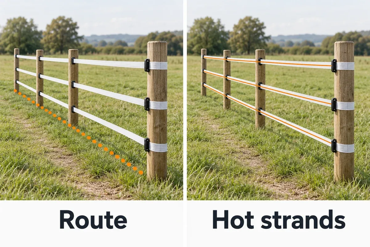
- Fence route length: the physical path of the boundary and other connected runs, counted once.
- Total hot-conductor length: the sum of the energized wire, tape, or rope on those runs.
For a uniform layout:
Total hot-conductor length = fence route length × hot-conductor countThe University of Maine’s electric-fence design guidance illustrates this with a one-mile perimeter carrying four energized strands: four miles of electrified conductor. That is useful information for your supplier, especially when the conductor is poly tape or rope.
Count only the strands connected to the energizer’s hot terminal. A deliberate ground-return wire belongs in the electrical design, but it is not a hot conductor. An unelectrified strand does not become hot because it sits beside one. Record insulated lead-out cable and underground gate crossings separately, since their length, insulation, and connections also affect the installation.
Do not count a shared dividing fence twice simply because it borders two paddocks. Do include separate branches that the energizer supplies simultaneously. For a complex layout, a small plan showing each run and connection is more useful to an installer than a single acreage figure.
Both panels below show the same example run. Keep these two measurements separate when discussing the finished layout with the supplier.
Check how the hot strands are connected
Several strands can provide parallel paths for the pulse when they are connected correctly. Virginia Tech’s energizer selection guide explicitly conditions its guidance on hot wires being connected at the beginning and end of each fence run. Under that arrangement, adding parallel wires can reduce resistance instead of requiring proportionally more joules.
Inspect connections with the energizer switched off. A rope that looks continuous may have a failed join, and a gate handle may interrupt one strand while another remains supplied. The wiring assumption does not hold simply because all the strands appear on the same posts.
Use the calculator’s unconfirmed-connections option if you cannot establish the layout. It will still total the lengths but will withhold the joule reference. Have the manufacturer or installer assess separately fed runs, unusual branching, and mixed conductor systems.
Understand the joule reference
Virginia Tech offers approximately one output joule per mile of fence route as a rough selection guide, subject to construction, soil, vegetation, and its parallel-wire assumption. It is a starting reference, not a law that predicts a charger’s performance on every installation. Virginia Tech: selecting an energizer.
For confirmed parallel hot wires, the calculator uses:
Planned route miles = present route miles × chosen length-expansion factor

Length-only output-energy reference ≈ planned route miles × 1 J per route mile
The hot-conductor count is used for the wire inventory. It does not multiply this output-energy reference.
These are different jobs. The inventory tells a supplier how much conductor is connected. The reference gives you a rough comparison point under a stated wiring assumption. The selected model still needs a manufacturer match for conductor resistance, vegetation, power supply, and ground return.
Worked example: a 1.5-mile, three-strand fence
This hypothetical example uses a 1.5-mile route, three hot conductors, confirmed connections at both ends, and a planned 20% route extension:
Present route:                         1.50 mi
Present hot-conductor length:          1.50 × 3 = 4.50 mi
Planned route with 20% more length:     1.50 × 1.20 = 1.80 mi
Planned hot-conductor length:          1.80 × 3 = 5.40 mi
Length-only output-energy reference:   approximately 1.80 J
The same present route is exactly 2.414016 km. The planned route is about 2.90 km, and its three hot conductors total about 8.69 km. Changing the measurement unit does not change the physical fence or the joule reference.
The 1.80 J reference is not an instruction to buy the next larger charger. A manufacturer may rate a lower-output model for that layout, or it may require a different model because of high-resistance tape and persistent vegetation. A dry return path may need a different grounding arrangement before extra output would help.
Take the manufacturer the planned route, conductor inventory, conductor specification, and seasonal conditions. Ask which published load category applies and what installed voltage should be maintained.
Why vegetation and soil do not receive fixed multipliers
Wet grass against a hot conductor provides a leakage path. More contact can reduce fence voltage, but “heavy vegetation” is not a measured resistance. A few blades, a wet hedge, and tape lying on the ground are different loads.
Maine advises that severe vegetation conditions may require higher joule capacity, while directing the owner to a fencing supplier for the appropriate charger. It does not provide a universal numerical adjustment for those conditions. University of Maine: joule requirements.
Soil presents a different problem. In an earth-return fence, the pulse must return through the animal, soil, and ground system. Dry or frozen ground can limit that return even when a meter shows voltage on the hot wire. A manufacturer-designed ground-return-wire arrangement may be needed where soil conductivity is poor. University of Maine: soil and wire ground return.
For that reason, the calculator changes the checks it recommends for vegetation and soil, while leaving its length-only reference unchanged. Choose equipment from a load rating that actually fits the site, then test the completed system.
Output joules, stored joules and voltage measure different things
Stored joules describe energy held inside the energizer before discharge. Output joules describe the energy delivered through its output stage. Losses inside the energizer mean those figures are different; there is no universal conversion ratio between them. Virginia Tech recommends output energy for comparison across brands. Virginia Tech: stored and output energy.
A model advertised simply as “2 joules” needs a closer reading. Is that 2 J stored, 2 J maximum output, or an output measurement at a particular test load? Keep the same kind of rating in the same comparison column.
Voltage answers another question: how much electrical potential is present at a measurement point. A high no-load voltage at the charger does not tell you what remains at the end of a long fence with grass leakage and poor connections.
| Specification or measurement | What it helps you assess | What it cannot establish on its own |
|---|---|---|
| Stored energy, J | Energy available inside that model before discharge | Energy delivered onto your fence |
| Output energy, J | Published pulse-energy capacity under the stated test conditions | Far-end voltage on your installed fence |
| No-load voltage, V or kV | Output with little or no connected fence load | Performance with your normal vegetation load |
| Voltage at a stated test resistance | Performance under that defined laboratory load | Every combination of fence wire, weeds, soil, and connections |
| Installed fence voltage | Conditions at the test point at that moment | Ground-return effectiveness or all-season containment |
If a datasheet includes a load curve, keep its voltage and resistance conditions together. Do not compare one model’s open-circuit voltage with another model’s loaded voltage.
A fence voltmeter normally measures pulse voltage. It does not convert that reading into output joules or certify the charger’s capacity. Use it to check the installation and follow changes along the fence.
Compare the result with an actual manufacturer rating
A useful comparison needs both energy specifications and a description of the fence behind the distance claim. Gallagher’s selection chart separates single-wire maximum distance, ideal multiwire distance, and multiwire distance under typical New Zealand conditions. Those columns describe different applications. Gallagher: mains and MBS selection chart.
| Gallagher model | Stored energy | Output energy | Multiwire, typical NZ conditions | Multiwire, ideal conditions |
|---|---|---|---|---|
| MBS100, G38910 | 1 J | 0.97 J | 3 km | 10 km |
| MBS200, G38911 | 2 J | 1.5 J | 5 km | 20 km |
| MBS400, G39010 | 4 J | 3 J | 8 km | 30 km |
The MBS100 product specification also lists 3 km as Gallagher’s multiwire recommendation and 10 km under ideal conditions. It supports mains, battery, or an appropriate solar installation. The solar kit is separate.
These are manufacturer ratings, not measurements of your pasture. The New Zealand chart’s typical-condition category cannot be assumed to cover every US horse fence, wide tape, winter climate, or weed load. Use the exact regional model and conductor guidance when making a purchase.
Cross-check: a three-kilometer multiwire route
Consider a hypothetical 3 km route with three hot wires, confirmed parallel connections, and no expansion:
Route:                               3 km = approximately 1.86 mi
Total hot-conductor length:           3 × 3 = 9 km, approximately 5.59 mi
Virginia Tech length-only reference:  approximately 1.86 output J
Gallagher MBS100 published output:    0.97 J
Gallagher MBS100 recommended route:   3 km multiwire
Gallagher’s published recommendation already covers a multiwire route. Multiplying its 3 km figure by the wire count would confuse route distance with conductor length. Conversely, demanding exactly 1.86 J as a minimum would reject a model its manufacturer recommends for a 3 km multiwire application under its stated conditions.
The comparison demonstrates why the calculator’s reference cannot select a model by itself. It also gives you a practical question for the supplier: does your conductor, wiring, vegetation, and climate fit the manufacturer’s 3 km category?
Zareba charger options for a US installation
The following existing options cover permanent AC supply and a compact solar system. Compare their output energy and the relevant vegetation limits before choosing one. The AC models are specified for a US 115 V, 60 Hz supply; they are not interchangeable with a 230 V mains model.
Zareba publishes separate distance figures for steel and polywire. The polywire figures below are manufacturer distance limits for that category, not approval for every horse tape or rope. Ask how your number of hot strands and the resistance of your chosen conductor affect those limits. For metric comparison, one mile is exactly 1.609344 km.
Compare power, output energy and vegetation conditions
-
Zareba EAC10M-Z 10-Mile AC Low-Impedance Fence Charger
Zareba
A low-impedance energizer with 0.5 output J and a 115 V, 60 Hz mains supply. Zareba's poly-fencing limits are 5 miles clear, 2.5 miles with light weeds and 1 mile with heavy weeds; confirm the conductor and multi-strand layout.
- 115 V, 60 Hz mains supply
- 0.5 output J
- Separate steel and poly-fencing distance limits
- Best for
- A maintained, modest permanent fence with a suitable US mains supply
- Power supply
- 115 V AC, 60 Hz
- Output energy
- 0.5 output J
- Polywire: light weeds
- Up to 2.5 mi (4.02 km)
- Polywire: heavy weeds
- Up to 1 mi (1.61 km)
-
Zareba EAC25M-Z 25-Mile AC Low-Impedance Fence Charger
Zareba
A low-impedance energizer with 1 output J and a 115 V, 60 Hz mains supply. Zareba's polywire limits are 12 miles clear, 6 miles with light weeds and 3 miles with heavy weeds; match the actual conductor and connected layout.
- 115 V, 60 Hz mains supply
- 1 output J
- Separate steel and polywire distance limits
- Best for
- A permanent US mains installation needing more capacity than the EAC10M-Z
- Power supply
- 115 V AC, 60 Hz
- Output energy
- 1 output J
- Polywire: light weeds
- Up to 6 mi (9.66 km)
- Polywire: heavy weeds
- Up to 3 mi (4.83 km)
-
Zareba EAC50M-Z 50-Mile AC Low-Impedance Fence Charger
Zareba
A low-impedance energizer with 2 output J and a 115 V, 60 Hz mains supply. Zareba's polywire limits are 25 miles clear, 12 miles with light weeds and 6 miles with heavy weeds; grounding and installed voltage still require testing.
- 115 V, 60 Hz mains supply
- 2 output J
- Separate steel and polywire distance limits
- Best for
- A longer permanent fence or greater seasonal load that exceeds the smaller AC models' ratings
- Power supply
- 115 V AC, 60 Hz
- Output energy
- 2 output J
- Polywire: light weeds
- Up to 12 mi (19.31 km)
- Polywire: heavy weeds
- Up to 6 mi (9.66 km)
-
Zareba Solar Electric Fence Charger, 5-Mile Low-Impedance Energizer
Zareba
The ESP5M-Z has 0.10 output J and a solar-charged 6 V battery. Zareba's polywire limits are 2.5 miles clear and 1.25 miles with light weeds, with no heavy-weed distance specified.
- 0.10 output J
- Solar-charged 6 V battery
- Clear or light-weed applications
- Best for
- Portable or remote horse-fence sections where solar power is necessary and the actual wire load is modest
- Power supply
- Solar-charged 6 V battery
- Output energy
- 0.10 output J
- Polywire: light weeds
- Up to 1.25 mi (2.01 km)
- Polywire: heavy weeds
- No distance specified
Distances are Zareba's published polywire limits for the stated vegetation category. Confirm the multi-strand layout, conductor resistance and exact model manual before purchase.
EAC10M-Z: a smaller permanent AC system
The EAC10M-Z has 0.5 output J. Zareba rates it for up to 10 miles of clear steel wire, while its poly-fencing figures fall to 5 miles clear, 2.5 miles with light weeds, and 1 mile with heavy weeds. Those categories show why the product name alone is a poor sizing method. Zareba EAC10M-Z specifications and distance guidance.
It is a candidate for a maintained, modest fence with reliable mains power and suitable grounding. A route that falls within one published distance still needs the multi-strand and conductor match. Leave room for the finished layout instead of buying at the edge of a vegetation limit.
Check current price on Amazon →EAC25M-Z: the middle AC option
The EAC25M-Z delivers 1 output J. Its published polywire distances are 12 miles clear, 6 miles with light weeds, and 3 miles with heavy weeds. The corresponding steel-wire figures are longer, so the 25-mile name should not be transferred to a horse-tape fence. Zareba EAC25M-Z specifications and distance guidance.
Compare this model when the smaller AC unit’s conductor-and-vegetation category leaves too little capacity for your planned route. It does not become the correct choice just because the length-only reference happens to be close to 1 J. Its actual installation still needs the required return path and fence voltage.
Check current price on Amazon →EAC50M-Z: more AC capacity for a verified need
The EAC50M-Z delivers 2 output J. Zareba’s polywire distances are 25 miles clear, 12 miles with light weeds, and 6 miles with heavy weeds, compared with a 50-mile clear-steel headline. Zareba EAC50M-Z specifications and distance guidance.
This is the larger AC option in this comparison, suited to investigating a longer route or a greater normal load than the smaller units cover. Confirm that poor insulation, gates, connections, or grounding are not the cause of an existing voltage problem before replacing the charger.
Check current price on Amazon →ESP5M-Z: compact solar power with a light-load limit
The ESP5M-Z has 0.10 output J and a solar-charged 6 V battery. Its five-mile rating is for clear steel wire. The manufacturer lists polywire limits of 2.5 miles clear and 1.25 miles with light weeds, with no heavy-weed distance stated. Zareba ESP5M-Z specifications and distance guidance.
That makes it a candidate for a maintained remote section that fits its light-load guidance. It is a poor comparison for persistent wet growth or an expanding system whose conductor load is uncertain. The lower output and weather-dependent recharge plan matter more than the five-mile name.
Check current price on Amazon →Choose a power system that can support the fence
The horse receives a pulsed fence output whether the energizer uses mains, battery, or solar power. The supply choice affects how reliably the unit can operate between checks and what equipment you must maintain.
Mains power for a permanent fence
When a suitable, dependable supply is available, a mains unit avoids routine battery charging. Match the model’s voltage and frequency, its permitted mounting location, and the required electrical protection. Have a qualified electrician assess the supply installation and any damaged building wiring.
Protect a mains energizer as its manual requires. A weather-resistant case does not automatically permit unsheltered installation. Plan access for inspection and enough space for the separate fence grounding system. Virginia Tech discusses sheltered siting and separation from residential or utility grounds in its energizer installation guidance.
Solar at a remote pasture
Solar equipment still runs from a battery; the panel replenishes it. Start with a model capable of the fence load, then check the manufacturer’s panel, battery, mounting, and seasonal operating requirements.
Winter shade and several dull days can change the power budget. Ask how many days the approved system can operate without useful solar charging, how it behaves at low charge, and whether any reduced-output mode changes the fence’s performance.
For a larger remote fence, compare a battery energizer with a matched solar panel as well as compact integrated units. Gallagher’s MBS series supports mains, battery, and solar supplies for the same energizer, while the appropriate panel and battery remain part of the system selection. Gallagher MBS100 power options.
Battery supply with a recharge plan
Use the battery voltage, chemistry, and capacity approved for the energizer. An input marked 12 V does not mean the fence operates at 12 V. The energizer produces a much higher, brief pulse at its fence terminal.
Plan how you will check charge, recharge or exchange the battery, and keep the fence operating during that work. Check the manual’s low-battery indication and any change in pulse rate or output. Do not size a solar panel from output joules alone: the manufacturer’s input consumption and operating conditions also matter.
Grounding must work before extra output can help
In a conventional earth-return arrangement, current must return from the horse through the soil and fence ground system to the energizer. An incomplete return path limits the system regardless of the output rating. Dry soil can make this especially difficult.
Choose the ground installation from the selected model’s manual and site conditions. The calculator gives no rod-count approval because it does not know rod depth, moisture, material, spacing, or the model’s grounding instructions.
Virginia Tech’s grounding-system guide describes a moist-soil arrangement with substantial rod contact and spacing. Its general guidance includes six feet of rod contact in moist soil, spacing of at least ten feet, and separation of at least 33 feet from utility grounds, service-box grounds, and metal water pipes. It also says poor-conductivity soil may need more grounding than the general minimum.
Those conditions are part of the guidance. Three short rods in dry gravel do not become an adequate system because they came in one kit.
Before installation, identify buried services and choose a location that can retain useful moisture. Check:
- The manual’s rod number, length, material, and connection requirements.
- Whether the intended rod depth actually reaches suitable soil.
- The required separation from other grounding systems, pipes, and structures.
- Compatibility of rods, wire, and clamps to limit corrosion.
- The manufacturer’s loaded-ground-test procedure and acceptable result.
If the recommended rods cannot be installed or the soil dries or freezes severely, have a fence specialist assess a different return-path design. Do not connect the fence earth to household grounding, a water pipe, or barn metalwork as an improvised solution.
Test the ground system under the prescribed load
A ground test needs the load and probe arrangement specified by the energizer or tester manufacturer. A reading taken with an unloaded fence may fail to reveal a weak ground system.
Read the full procedure before creating a test load. Keep horses and people clear, switch off before changing connections, and use a meter designed for pulsed electric fencing. If you cannot establish the required test conditions safely, have an installer perform the test.
A failed ground test calls for work on the return path. Replacing the energizer first can leave the fault in place. Test again during the driest normal season, when an installation that worked after spring rain may behave differently.
Agree a horse-fence voltage target for the installation
The relevant reading is on each hot conductor where the horse could contact it, including the farthest supplied sections. A strong reading at the charger is only the beginning of the check.
Zareba’s horse-fencing guidance gives a minimum fence-line range of 2,000–3,000 V, and identifies vegetation, fence length, and tape or rope type as factors affecting that reading. This is its horse-specific minimum guidance, not a promise that a fence holding 2,000 V will suit every horse or site.
Virginia Tech’s energizer selection guide gives ideal minimums of 5,000 V for cattle and 7,000 V for sheep. Those are the species named by that source; they do not establish a universal 5,000 V acceptance threshold for horse fencing. Virginia Tech: species and fence voltage.
Use the selected energizer and conductor manufacturer’s horse guidance, the fence design, and advice from the installer to agree an operating target and an action threshold. Thick coats, difficult ground return, and seasonal leakage belong in that discussion. The calculator cannot derive a voltage target from route length.
Measure in a sequence that reveals the problem
Use a purpose-made electric-fence pulse meter with a suitable measurement range. Follow its instructions for contact points and earth probe placement. Do not test the fence with your body or use a household multimeter for these pulses.
- Prepare a secure holding area. Keep the horse away from a boundary being tested or repaired.
- Check the energizer’s supply and output. Follow the manual’s unloaded-output procedure, switching off before disconnecting or reconnecting leads.
- Test the ground system. Use the specified test load and probe arrangement.
- Check the start of the fence. Measure after the lead-out connection on every hot conductor.
- Check the farthest supplied sections. Include branches, internal divisions, and points beyond gate crossings.
- Compare the readings with the agreed target. Recheck after normal regrowth or dry conditions, rather than relying only on a newly cleared, wet-soil installation.
| Measurement pattern | What to investigate next |
|---|---|
| Weak unloaded output at the energizer | Supply, battery, approved operating mode, or energizer fault |
| Normal energizer output, failed ground test | Ground rods, connections, soil contact, or return-path design |
| Good reading before a gate and a lower reading after it | Gate lead, underground cable, joins, and continuity of each hot strand |
| One hot conductor reads much lower than the others | That conductor’s feed, joins, insulation, and vegetation contact |
| Far end is below the target although the energizer is strong | Connected load, vegetation, conductor resistance, lead-out cable, and layout |
| Performance falls only as growth or drought develops | Seasonal leakage and grounding, then manufacturer capacity for that condition |
A substantial voltage loss accompanied by increased current can help identify a leakage fault; Virginia Tech describes this diagnostic pattern in its electric-fence troubleshooting guide. A basic voltage meter can show where performance changes, while a current-reading fault finder provides more information about the direction of a fault.
Once the ground system, connections, and conductor condition pass their checks, compare the remaining normal load with the manufacturer’s model rating. Use the weak horse-fence troubleshooting sequence for the repair steps before deciding on replacement.
Tools for checking the installation
A pulse-voltage meter is useful even when the energizer is new. It lets you record conditions at the charger, gates, and far end so that later readings have a meaningful comparison.
The Gallagher Smartfix combines voltage measurement, current measurement, and fault-direction indication. That helps on branching fences where a voltage reading alone leaves several possible fault paths. Gallagher’s fault-finder instructions explain the measurement slot, current direction, and checks at branches. Follow the instructions for the exact instrument you buy.
The Gallagher A655 provides a set of three galvanized ground rods and connection hardware. It is useful when those components match an already established ground-system plan. The number in the kit does not approve the design for your energizer or soil. Gallagher grounding equipment.
Measurement and grounding hardware
-
Gallagher Smartfix Fence Volt & Current Meter
Gallagher
A digital pulse-fence meter combining voltage and current measurements with a fault-direction indicator. Use it to follow leakage on connected runs and branches, following the instrument's test instructions.
- Voltage and current readings
- Directional arrows for following a fault
- Fault-finding support
- Best for
- Longer or fault-prone fences where voltage alone does not show where current is escaping
- Function
- Directional fault-finding meter
-
Gallagher A655 Complete 3-Ground Rod Electric Fence Kit
Gallagher
A set of three galvanized ground rods with connection hardware. Use it when the components match the selected energizer's ground-system plan; kit count alone does not establish suitable grounding.
- Three galvanized ground rods
- Connection hardware included
- Match rod depth, spacing and material to the installation plan
- Best for
- Grounding hardware after the energizer manual and site plan establish the required rods and materials
- Function
- Complete rod-and-connection kit
Choose the meter from its pulse-fence instructions and the grounding hardware from the selected energizer's site-specific ground-system plan.
Persistent shocks from gates, building metalwork, water systems, or areas outside the intended electric fence need qualified investigation. Virginia Tech’s troubleshooting guide discusses stray voltage and the need for a certified electrician. Stop treating that problem as an ordinary charger-sizing issue. Virginia Tech: stray voltage.
Keep a record of the conditions the fence passed
Record the model, output-energy specification, hot-wire layout, and the locations where you measured voltage. Add the soil condition, vegetation condition, battery state if relevant, and the agreed action threshold.
A reading after rain and mowing is a useful baseline, but it does not describe a dry summer with regrowth. Recheck after connecting an extra paddock, adding a temporary run, changing conductor type, repairing a gate crossing, or changing the power system.
A simple log needs only:
| Date and conditions | Energizer output | Ground-test result | Near-end readings | Far-end readings | Action taken |
|---|---|---|---|---|---|
| Record soil moisture, growth, and battery condition | Use the manual’s test method | Use the prescribed load | Record each hot strand | Include the farthest branch | Repair, clear, recharge, or seek help |
If the far-end reading falls below the agreed threshold, secure the horse and investigate. A familiar charger sound, an illuminated status lamp, or a previous successful test does not establish today’s fence condition.
Frequently asked questions
How many joules does a horse fence need?
There is no output-joule number that fits every horse fence. Start with route length, conductor type and connections, vegetation, ground return, and the manufacturer’s loaded-fence guidance. Virginia Tech’s approximate 1 J per route mile is a conditional reference for correctly connected parallel hot wires. The installed fence must still pass its grounding and voltage checks.
Do three hot strands need three times as many joules?
They contain three times as much conductor as one strand on the same route, but the energy requirement does not automatically triple. Virginia Tech explains that hot wires joined at both ends can reduce resistance. Keep total conductor length in the supplier’s inventory and use the correct multiwire rating.
Can a model below the output-energy reference still suit the fence?
A model below the length-only reference may be suitable when the manufacturer rates it for the actual layout and conditions. The MBS100 comparison is an example of a 0.97 output J model with a published 3 km multiwire recommendation. Treat the difference as a reason to check the manufacturer’s conditions, not as approval for every three-kilometer horse fence.
Should I add more joules for dry soil?
Dry soil calls for a return-path assessment and a loaded ground test. A fixed extra percentage cannot restore conductivity. After the ground system works, check whether the energizer also has enough capacity for the connected conductor and normal vegetation load.
Is a 5,000 V reading enough to approve my horse fence?
A single voltage reading cannot approve the installation. Agree a horse-specific target from the equipment guidance and site design, measure every hot conductor at relevant contact points, and perform the prescribed ground test. A high reading near the charger can coexist with a weak far end or a poor return path.
When does a larger energizer make sense?
When the existing unit works correctly, the ground system passes its test, faults have been repaired, and the planned connected load exceeds the model’s applicable rating. A documented extension or greater normal seasonal load can justify more capacity. Match the replacement’s grounding and power requirements too.
Can I connect two energizers to get more capacity?
Do not connect two energizers to the same fence circuit. Virginia Tech warns that overlapping pulses remove the protection of a pulsed system and can damage equipment. Have a qualified installer design any independently energized sections and the required separation. Virginia Tech: energizer installation.
Before ordering, give the supplier your route plan, conductor specification, hot-wire connections, planned extension, soil conditions, and normal vegetation load. Ask for the applicable model rating and ground-test instructions, then keep the far-end voltage target with your maintenance records.
Sources and further reading
- Virginia Tech: How to Select and Install an Energizer
- University of Maine Cooperative Extension: Electric Fence Design
- Gallagher: Mains and MBS Energizer Selection Chart
- Gallagher: MBS100 Specifications
- Zareba: Horse-Fencing Guidance
- Virginia Tech: How to Install a Grounding System
- Virginia Tech: Electric-Fence Troubleshooting