

 Published sources
 Product details checked
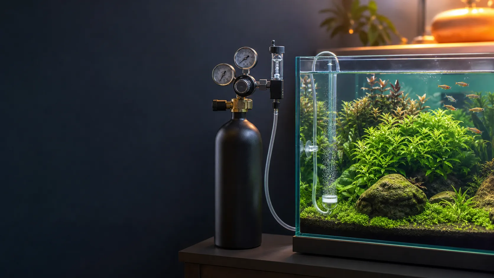
Start with a filled bubble counter and a solenoid that should be on. If the counter has no bubbles, check its liquid, power, gas supply and metering valve, then consider a blockage farther along the line. If the counter bubbles but the diffuser stays quiet, check the tubing, check valve and diffuser before changing the regulator. Missing working pressure, unstable output or unusually fast cylinder loss needs a separate supply and leak check.
This guide covers pressurized CO₂ systems for freshwater planted aquariums. Cylinder and regulator instructions do not apply to fermentation bottles or chemical CO₂ generators; use those systems’ own operating and pressure-release instructions.
If fish are gasping at the surface after a CO₂ adjustment, stop the CO₂ supply and start aeration immediately. The ADA Count Diffuser manual gives this response to excess CO₂ and also identifies reduced shrimp feeding activity as a warning sign. Persistent distress needs water-quality checks and help from an aquatic veterinarian; do not resume dosing while animals remain distressed.
For a substantial gas leak, close the cylinder valve only if you can do so safely. Leave the area if the leak continues or anyone feels unwell, and seek emergency help. CO₂ has no reliable smell warning and can accumulate in poorly ventilated spaces. OSHA’s CO₂ hazard guidance explains that elevated CO₂ can be dangerous even when oxygen is present. Keep the cylinder restrained upright in a ventilated location, as described in NIH’s compressed-gas guidance.
Find your starting point
A bubble counter is a visible checkpoint in the gas line. It can help locate a fault, but bubbles at that checkpoint do not prove that CO₂ reaches the aquarium. Equally, a stopped counter can result from a downstream restriction once pressure builds against it.
| What you can see | Where to start | What the result tells you |
|---|---|---|
| The counter has lost its liquid | Refill it using its own instructions after safe shutdown | An empty chamber cannot show a normal bubble count; gas may still be passing |
| A filled counter has no bubbles during the scheduled on period | A. No bubbles in a filled bubble counter | Power, supply, metering or a downstream restriction needs checking |
| The counter bubbles, but an in-tank ceramic diffuser produces nothing | B. Counter bubbles, diffuser stays quiet | Follow the gas path beyond the counter, including possible leaks |
| An inline system has little visible mist | Check the filter return and the type of diffuser in section B | Visible mist alone cannot establish how much CO₂ is dissolved |
| Working pressure is missing, output drifts or the cylinder empties unusually quickly | C. Cylinder, regulator and leak checks | The supply or pressure control needs attention before further tuning |
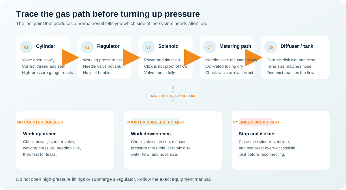
For a specific task, jump to diffuser cleaning, restart checks, repair or replacement, or the fault log.
Before touching a connection
Identify the regulator model, diffuser model and any separate check valve. Find the instructions for shutdown, releasing trapped pressure, permitted working pressure and user-serviceable connections. A regulator’s pressure-adjustment knob and needle valve do different jobs: the knob sets delivery pressure; the needle valve meters gas flow.
A closed cylinder valve does not make the regulator or tubing pressure-free. A solenoid, shut needle valve or blocked diffuser can trap gas. FZONE’s Mini regulator troubleshooting instructions explain this trapped-pressure condition. Follow your equipment’s depressurization procedure before removing tubing, opening a counter or changing a seal. A gauge at zero does not prove that every downstream chamber is empty; check the whole procedure. If a blockage prevents safe pressure release, stop and contact the manufacturer.
Keep electrical plugs and adapters dry. Do not open a regulator body, solenoid housing, gauge port, cylinder valve or safety device as part of these checks. Internal work needs the manufacturer’s instructions for the exact unit and its authorization where required. A troubleshooting page for a similar-looking device is insufficient.
A. No bubbles in a filled bubble counter
1. Separate an empty chamber from a stopped gas supply
Look closely at the counter before interpreting its output. There must be enough of the specified liquid to cover the point where gas enters. If the chamber is dry, an apparently motionless counter tells you little about gas flow.
For a CO2Art regulator-mounted counter, use water: the counter installation manual discourages mineral oil because it can contaminate the diffuser. Follow the filling instructions for another brand rather than transferring that rule to every counter. Shut down and release pressure before opening the cap, and keep the required seals in their intended positions.
After reassembly, check the cap and tube connection for leaks as instructed. If the counter repeatedly loses liquid, record how quickly it happens and inspect the seals and tubing route. Refilling restores the observation point; it does not fix whatever is emptying it.
2. Check power during an intended on period
The solenoid is the electrically operated shutoff valve. Check the timer’s current time, schedule and manual-on setting, if it has one. A smart-plug display saying “on” is only a command; verify that the adapter and low-voltage lead are connected and that any fitted indicator responds normally. If a pH controller operates the solenoid, check whether it is intentionally withholding CO₂ before diagnosing a hardware failure.
Use the normal external controls to switch the solenoid once. A click is useful evidence that something moved, but it cannot confirm an open gas passage. CO2Art’s no-bubbles troubleshooting guide directs owners to support if the energized solenoid does not click.
An absent click after the schedule and connections are checked leaves a power-supply or valve problem to resolve. Use only an electrically compatible replacement adapter specified for the device. Do not open the coil, bypass a controller’s safety function or improvise a connection to mains power.
3. Check the metering valve without losing your baseline
If the solenoid should be open, read the working-pressure gauge and compare it with the last normal setting. Follow section C if pressure is absent or abnormal. Opening the needle valve cannot restore pressure that the regulator is failing to deliver.
When pressure is appropriate for the installed equipment, check whether the needle valve was closed during a cylinder change or maintenance. Follow its manual for the opening direction and adjustment. Photograph the starting position and change it only a little at a time. For the CO2Art Pro-SE, the setup manual specifies a pause between adjustments and a longer settling period after startup. Other valves can respond differently; a full turn is not a transferable dosing instruction.
If bubbles return, observe the diffuser and aquarium before adjusting again. If they do not, a closed or obstructed path beyond the counter remains possible. Avoid making several large adjustments that could release a sudden high flow when the restriction clears.
4. Use a downstream isolation test only where the manual permits it
For its own equipment, CO2Art’s no-bubbles guide uses removal of the tubing beyond the counter to distinguish downstream resistance from a counter or metering fault. This is a useful test when the outlet is user-serviceable and you can carry out the specified shutdown and pressure release.
Close the cylinder and depressurize using the applicable instructions before detaching that outlet tube. Then perform only the brief, controlled test permitted by the manufacturer in a ventilated area, keeping the gas discharge away from the aquarium. Shut down and depressurize again before reconnecting. Do not remove a pressurized counter, loosen a cylinder connection or fully open a needle valve into the aquarium.
Interpret the result at the checkpoint you actually tested:
- If a correctly filled counter bubbles with its downstream tube disconnected, the cylinder and upstream controls can supply gas at that moment. Inspect the detached path for a reversed check valve, kink, leak or blocked diffuser.
- If it still does not bubble, the counter’s own integrated check valve can be blocked, as well as an upstream supply being faulty. A silent counter alone cannot distinguish them.
- If pressure cannot be released or the outlet is not designated for this test, give the manufacturer the observations and gauge readings. Do not expand the test into internal disassembly.
Compare the two checkpoints below during an intended on period. If they differ, trace the downstream path rather than assuming that more pressure is the answer.
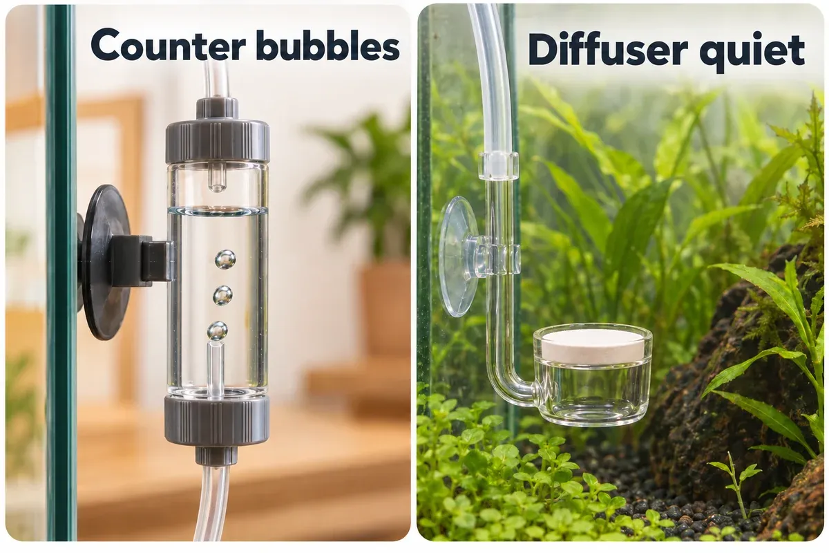
B. Counter bubbles, diffuser stays quiet
Follow the tube from the counter to the aquarium. Note where each check valve sits, where water begins and whether bubbles escape anywhere other than the diffuser membrane. Gas entering the counter can be lost through a connection farther along the line.
1. Check valve direction and the location of any water
A check valve permits gas toward the aquarium and blocks water coming back. Its arrow must point in the CO₂ flow direction, usually from the regulator toward the diffuser. The Dennerle CO₂ Safety Stop manual shows that direction and explains how valve placement affects morning startup.
Water on the aquarium side of a functioning check valve can be normal after shutdown. In the Dennerle setup, a valve near the regulator leaves a longer tube section that can fill with water; restarting at a low gas rate can take longer to clear it. A valve closer to the aquarium limits that returning column. Use your valve’s installation instructions rather than relocating every valve by the same rule.
Water crossing the valve onto the protected regulator side is a different finding. Stop the system and have a wet regulator or solenoid assessed before reuse. Drying the outside does not establish that its internal parts are serviceable.
Check whether the counter already incorporates a non-return valve. Extra valves add another possible restriction, but an integrated valve does not justify removing required backflow protection. If the manual permits an isolation check, compare the suspected valve with a known-compatible replacement while following the shutdown procedure. Do not test it by mouth or leave the system operating without the required protection.
2. Inspect tubing and fittings before changing pressure
Look for a sharp bend behind the cabinet, a trapped tube under equipment, a split tube end, or a connection that has partly pulled out. Reposition an intact external tube gently; make connection changes only after depressurizing. A kink or loose joint can explain a failure that began after moving the cylinder or cleaning the tank.
Match the tube material, dimensions and pressure rating to each connection. The CO2Art Inline Diffuser instructions require pressure-rated, acid-resistant CO₂ tubing and exclude silicone tubing for that device. A generic air-pump tube is not an equivalent substitute.
There are deliberate exceptions for specific glassware. The ADA Count Diffuser manual requires pressure-resistant tubing into its check valve and a silicone connection to the glass diffuser. Forcing stiff tubing onto that glass fitting would contradict the instructions. Follow the complete tubing arrangement for your model, including any prescribed transition at the check valve.
Do not push aquarium water back toward the regulator to “clear” the tube. If the manufacturer allows removal and draining, do that after isolation and pressure release, then inspect the valve that should protect the regulator. A water-filled section downstream of a functioning valve may simply need the normal startup period.
3. Check the pressure requirement for the actual diffuser
Ceramic membranes resist gas flow. A regulator can show pressure while the diffuser receives too little pressure to pass gas. A restricted valve, leak or obstructed tube can also prevent the expected result.
For a CO2Art Pro-SE supplying a compatible high-pressure inline atomizer, the Pro-SE setup manual gives 30–40 psi, approximately 2.1–2.8 bar. The CO2Art Inline Diffuser specifies a minimum of 30 psi. These are matched equipment references, not a setting for every ceramic diffuser. Confirm the pressure limits of the regulator, tubing, valves and diffuser together before using that range.
If this same combination previously worked at the correct pressure and now stops, check for a leak or fouled membrane before raising the setting. A requirement above any component’s permitted pressure is a compatibility or service problem. Do not use the regulator’s maximum as a troubleshooting target.
Adjust working pressure only by the procedure in your regulator manual. Keep the needle valve at a conservative metering setting, make one change, and allow the specified settling time. If pressure is within the permitted range but output remains absent, continue with membrane and flow checks rather than repeatedly increasing it.
4. Separate a new membrane’s startup from a dirty membrane
A new or dried diffuser may need soaking before it produces its intended mist. For the acrylic-and-ceramic Tropica CO₂ Diffuser, soak it in water for 24 hours before use. That duration belongs to the Tropica model; use the supplied instructions for another diffuser.
If the problem started after replacement, confirm the soaking requirement, connection, counter filling and model compatibility. If an established diffuser gradually produced coarser bubbles or less output, inspect for deposits, algae or damage. These histories point to different checks even when the final symptom looks identical.
Bubbles escaping around a membrane’s edge, through a crack or at a gas inlet need attention to the body and seal. A large bubble leaving a damaged joint does not show that the ceramic pores are working. Remove a damaged diffuser from service after safe shutdown.
5. Check an inline diffuser’s water path separately
An inline diffuser injects CO₂ into flowing return water rather than releasing it from a visible disk in the tank. Confirm that the filter is running and water reaches the return. Weak return flow needs its own filter and hose diagnosis; adjusting CO₂ cannot restore circulation.
Check the specified return-hose size and the installation arrangement. Follow flow-direction markings where the model has them. Before opening a return hose or diffuser body, use the filter’s shutdown and hose-isolation procedure as well as the CO₂ system’s pressure-release procedure. After reassembly, check for water leaks before restarting the gas.
Distinguish a ceramic inline atomizer from a reactor designed to dissolve gas within a chamber. The visibility of bubbles at the return differs between these devices. Inspect the gas supply and use a suitable CO₂ indicator instead of declaring failure solely because there is no obvious mist. The Pro-SE manual treats reactors and high-pressure atomizers as different operating cases.
C. Cylinder, regulator and leak checks
Read cylinder pressure and working pressure separately
On a two-gauge regulator, the cylinder-side gauge reads inlet pressure; the working-pressure gauge reads delivery-side pressure. Follow the labels and manual, because position and layout vary. A gauge is not a flow sensor: a reading can remain when a shut valve has trapped gas.
CO₂ stored as a liquid can maintain a fairly steady cylinder pressure while liquid remains. CO2Art’s cylinder-pressure explanation describes why the gauge does not gradually count down like a fuel gauge. Once pressure starts falling near depletion, arrange a refill or exchange; the remaining running time depends on use. Ask your gas supplier to confirm the cylinder’s contents if the reading is uncertain.
| Gauge behavior | What to establish next |
|---|---|
| Cylinder gauge shows little or no pressure during correct operation | Confirm the valve position, correct cylinder connection and refill status using the regulator manual and gas supplier |
| Cylinder pressure is present but working pressure remains absent | Confirm the model’s startup sequence; if correct, request service rather than opening the regulator |
| Working pressure remains high after turning the adjustment down | Check whether gas is trapped behind closed controls or a restriction; use the prescribed pressure-reduction procedure |
| Working pressure changes unexpectedly during use | Stop further dosing adjustments, note cylinder condition and readings, and ask for a regulator check |
For CO2Art Pro-SE and Pro-Elite units, the pressure-reduction guidance explains that lowering the setting does not instantly remove stored outlet pressure. Let it settle by the prescribed method. Do not unscrew a gauge or fitting to force the needle down.
Two pressure gauges and two pressure-reduction stages describe different features. If you are considering a replacement because delivery varies as the cylinder empties, check its actual stage design and operating range. A dual-stage regulator still cannot repair a leaking joint or a blocked diffuser.
If the problem began immediately after a cylinder change
Check the connection standard and sealing arrangement against the exact regulator version. CGA320, W21.8, paintball connections and disposable-cartridge fittings are not interchangeable by appearance. Use only a manufacturer-approved adapter; do not force mismatched threads.
The CO2Art Pro-SE manual distinguishes a washer-based connection from its newer CGA320 stem with a black O-ring, which needs no separate washer. Adding another washer is not an automatic cure. Identify which stem you have before changing a seal, and use the specified replacement and tightening method after pressure release.
A failure straight after refitting also warrants a check of the timer connection, needle-valve setting and external joints. Inspect those before assuming that the cylinder refill damaged the regulator. Never adjust or repair a cylinder valve yourself; refer a cylinder fault to the gas supplier.
Check accessible joints for leaks
A bubbling counter with a silent diffuser can be losing gas between the two. Unusually short cylinder life is another reason to inspect connections, although changed operating hours or dosing can also increase consumption.
Use the leak-check method permitted for your equipment. CO2Art’s regulator-mounted counter manual specifies a soap-and-water mix for the assembled connection. Check whether your regulator permits that solution or requires a particular leak-detection fluid before applying it elsewhere.
For an external check at normal permitted operating pressure:
- Keep the cylinder secured and use only the startup procedure in its regulator manual. A substantial uncontrolled leak is a shutdown problem, not a reason to continue testing.
- Apply the permitted fluid sparingly to accessible external gas joints, keeping it away from electrical parts, gauge interiors, vents and aquarium water.
- Watch for bubbles that continue to grow at one point. Foam introduced while applying the fluid is not the same finding.
- Mark the joint, close the cylinder and release pressure by the manual before correcting a user-serviceable tube connection or seal. Do not tighten or unscrew it while pressurized.
- Clean off the test fluid as instructed, reassemble and repeat the approved check. A persistent leak requires service or the correct replacement part.
Do not submerge the regulator or solenoid. Leave a leak at a regulator body, gauge port, safety device or cylinder valve to the manufacturer or gas supplier. OSHA’s guidance calls for maintenance by qualified personnel following the manufacturer’s instructions.
Distinguish residual bubbles from a solenoid that will not close
Some gas remains downstream after the solenoid switches off, so a brief continuation of bubbling can be normal. Record whether the rate falls and whether it stops within the unit’s expected period. FZONE’s Mini regulator guidance describes residual-pressure bubbling; use the timeframe for your model rather than imposing one delay on every system.
Continued flow beyond that period, especially at an unchanged rate, needs a shutoff-valve check. Close the cylinder while arranging service. CO2Art’s page titled Solenoid Verification Procedure concerns dirt preventing full closure. It is not proof that every no-bubble fault needs solenoid cleaning, and its internal procedure is not transferable to another brand or revision.
Clean a diffuser with the method for that model
Clean when deposits affect output or the manufacturer’s maintenance instructions call for it. First establish that gas reaches the diffuser and that its pressure requirement is met. Cleaning the disk will not fix a reversed valve or a leaking outlet tube.
Before removal, shut down and release gas pressure as directed. For an inline unit, also isolate the filter hoses as instructed. Identify which parts may be soaked: a removable ceramic membrane, a complete glass diffuser and a body containing metal or seals may need different treatment.
| Diffuser or material | Applicable cleaning guidance | What to keep specific |
|---|---|---|
| CO2Art inline diffuser covered by its cleaning guide | CO2Art’s inline cleaning instructions describe three parts water to one part bleach, a soak of several hours, then rinsing | Confirm the method, bleach strength and soakable parts for your revision, particularly a version with a metal body or replaceable membrane |
| Aquario Neo diffuser covered by Aquarium Co-Op’s instructions | Aquarium Co-Op’s published Neo method uses equal parts water and bleach for 5–10 minutes, followed by fresh water and its specified dechlorinator | That method keeps gas running during the soak; follow the complete procedure only for a compatible Neo model and approved cleaner strength. The ratio is a dilution of a bleach product, not 50% active chlorine |
| ADA Count Diffuser glassware | Its manual specifies Superge cleaner, removal of suction cups and silicone tube, then thorough rinsing including the chamber | Follow the cleaner’s directions; the manual prohibits brushing the membrane and using boiling water |
| Another diffuser, or an unidentified model | Obtain its manufacturer-approved cleaner, dilution, contact time and rinsing method | A similar name, acrylic body or ceramic disk does not establish compatibility |
These methods differ substantially. Do not substitute the longer CO2Art soak for the shorter Neo procedure or apply either recipe to every “Neo-style” diffuser. If the instructions do not identify the cleaner strength or the permitted parts clearly enough for your unit, ask the manufacturer before making a chemical soak. An acrylic body alone is not a universal reason to allow or prohibit bleach.
Keep all cleaning outside the aquarium. Never mix bleach with vinegar, citric acid, ammonia or another cleaner. Follow the cleaner’s protective-equipment and ventilation instructions; the CDC’s bleach safety guidance explains the risk of mixing products.
Complete every rinse and any required dechlorination stage before reinstalling. A neutralizing conditioner must be used at the concentration and contact time specified by the applicable instructions. Inspect the body, membrane and seals for cracks or deterioration. If cleaning fails, replace the approved removable membrane where available; replace a damaged sealed diffuser instead of increasing pressure to compensate.
Restart the system and check the aquarium
Treat a cleaned diffuser or replaced valve as a fresh adjustment. A cleared restriction can pass more gas than it did before service, so yesterday’s needle-valve position may now produce a different dose.
- Reassemble according to the equipment manuals, with backflow protection and the correct tubing. For an inline device, restore water circulation and check for water leaks first.
- Set working pressure within the limits of the installed combination, then start with a conservative metering setting using the regulator’s instructions. Complete the approved gas-leak check.
- Confirm both the counter’s behavior and output at the diffuser or return. Keep watching the livestock while the system settles.
- Adjust flow only after the model’s startup period. The Pro-SE manual specifies 5–30 seconds between adjustments and at least 30 minutes after solenoid startup before further tuning for that regulator. Those are equipment timings, never a waiting period for distressed fish.
- Check the aquarium’s CO₂ indicator after its response period and observe another normal shutoff and startup before considering the fault resolved.
Bubble rate is a reference for your setup
There is no reliable conversion from “one bubble per second” to a universal dissolved CO₂ concentration. Counter designs produce different bubble sizes, and water circulation, dissolution, surface exchange and plant uptake differ. CO2Art’s drop-checker guidance explains those limits and the indicator’s delayed response.
Use the counter to record repeatable flow on the same equipment. Use a drop checker with the prescribed reference solution and color scale to assess dissolved CO₂; do not fill it with aquarium water unless its own instructions require that. Read it at comparable times in the cycle. It cannot provide an immediate warning after a valve adjustment, and a reassuring color never overrides distressed fish.
Tank-water pH and carbonate hardness can help explain CO₂ behavior, but other acids and buffers can distort a simple pH/KH estimate. Do not tune to an arbitrary pH or force the checker toward a color borrowed from another test solution. Choose settings for the plants, livestock and equipment in your own aquarium.
Keep light and circulation steady while troubleshooting
Hold lighting settings steady while resolving gas delivery. Brighter light can increase the plants’ demand for CO₂; Tropica’s fertiliser and CO₂ guidance explains the role of added CO₂ for its more demanding plant categories. Changing the light, gas rate and fertilization together makes the cause of a response harder to identify.
Restore normal circulation so gas reaches the planted areas, while retaining appropriate surface movement for the livestock. Do not suppress gas exchange simply to make the drop checker change color. If the tank also has green aquarium water, check its light and nutrient inputs separately after restoring the CO₂ supply; a working diffuser does not establish why the water turned green.
Decide what to repair or replace
Buy a part only after the checks point to it. Match the replacement to the rest of the system rather than replacing several components at once.
| Established finding | Appropriate next step |
|---|---|
| A tube is kinked, split or leaking at a serviceable connection | Reroute or replace it with the specified material and size, then repeat the approved leak check |
| A check valve is reversed, leaking backward or restricting flow in an approved isolation test | Correct its installation or fit a CO₂-compatible valve that meets the model’s requirements |
| Gas reaches a fouled diffuser at its permitted pressure | Use its approved cleaning method; replace the membrane or diffuser if cleaning fails or damage is visible |
| An adapter or solenoid fault remains after external power checks | Obtain the manufacturer’s compatible power supply or authorized valve service |
| Working pressure remains absent or unstable after correct setup | Request regulator service; compare an appropriately rated replacement only if repair is unsuitable |
| The cylinder supply is exhausted or its valve is faulty | Arrange refill, exchange or inspection with the gas supplier |
For a new regulator, match the cylinder connection, sealing system, diffuser pressure requirement and electrical supply. For an inline diffuser, also match the return-hose dimensions and service access. Before buying a cylinder, confirm that your local supplier accepts that valve and cylinder for refill or exchange. A compatible repair can be enough; a more expensive regulator cannot clear a dirty membrane.
Keep a short fault log
Use this as a record of your observations, not a list of target settings. Photograph gauge positions and the tube route before making a change. Recheck at the same point in the operating cycle so you do not compare initial pressurization with fully settled output.
| Checkpoint | Before the change | After one change |
|---|---|---|
| Regulator, diffuser and check-valve models | Record exact models and revisions | Record only the part changed |
| Schedule, elapsed time since startup and solenoid power | Record time and visible indicators | Compare at the same startup stage |
| Cylinder and working-pressure readings, including units | Photograph and note both readings | Note whether pressure settles normally |
| Counter liquid and bubble behavior | Record liquid level and observed flow | Note whether the same counter behaves consistently |
| Water in the line and valve direction | Mark which side of the check valve is wet | Confirm that the protected side stays dry |
| Diffuser output, return flow and approved leak check | Describe the observation and any leaking joint | Record the result after reassembly |
| CO₂ indicator and livestock behavior | Note the time of the reading and behavior | Recheck after the indicator delay; act immediately on distress |
Once output is stable, keep the normal pressure, counter behavior and schedule as your baseline. Inspect valve direction and tubing during maintenance, follow the diffuser’s cleaning instructions, and leak-check connections whenever you change them. Use the check valve’s own inspection interval; different valve designs have different maintenance requirements.
If the fault persists, send the manufacturer the model names, gauge photos, power observations, water location and result of any permitted isolation test. That evidence helps separate a supply fault from a blocked counter, valve or diffuser without opening the pressure equipment.
Common questions
Why did the diffuser stop after I changed the cylinder?
Check the connection’s correct seal, the cylinder valve, working-pressure setup, needle-valve position and solenoid power. A disconnected adapter or wrong washer arrangement can appear at the same time as a refill. Follow the regulator version’s instructions before changing parts.
Why does CO₂ take longer to start each morning?
The line may need to repressurize and clear water on the aquarium side of its check valve. Compare startup at the same gas setting and check-valve position. A growing delay also warrants an inspection for leaks, obstruction or valve failure; water crossing onto the protected side needs a shutdown.
Can a drop checker stay green when the diffuser has stopped?
Yes. Its color responds with a delay, and dissolved CO₂ already in the water does not disappear as soon as gas delivery stops. Diagnose the gas path directly instead of using one color reading to prove that equipment is running.
Can I use an air pump to test the ceramic disk?
Use only the test permitted by the diffuser manufacturer. The ADA Count Diffuser manual specifically excludes connection to an air pump. An unsuccessful improvised test cannot tell you whether the membrane will work at its specified CO₂ operating pressure.
Do I need to clean the solenoid whenever there are no bubbles?
No. Check power, supply, the filled counter and downstream restrictions first. Continued gas flow after shutdown is another symptom with its own valve check. Internal cleaning belongs to the procedure for the exact unit and should be arranged with the manufacturer.
Sources and further reading
- CO2Art: Pro-SE setup, sealing arrangements and adjustment timing
- CO2Art: no bubbles after the solenoid switches on
- CO2Art: regulator-mounted bubble counter installation
- CO2Art: Inline Diffuser pressure and tubing requirements
- CO2Art: cylinder pressure while liquid CO₂ remains
- CO2Art: lowering working pressure on Pro-SE and Pro-Elite
- CO2Art: solenoid verification for incomplete closure
- CO2Art: inline diffuser cleaning
- CO2Art: drop-checker response and bubble-rate limitations
- FZONE: Mini regulator troubleshooting
- Dennerle: CO₂ Safety Stop manual, including English instructions
- Tropica: acrylic CO₂ Diffuser and initial soaking
- Tropica: fertiliser and CO₂ for planted aquariums
- Aquarium Co-Op: cleaning its Aquario Neo diffuser
- ADA: Count Diffuser manual, including English maintenance and livestock warnings
- OSHA: CO₂ exposure and maintenance hazards
- NIH: compressed-gas handling and ventilation
- CDC: precautions when using bleach