
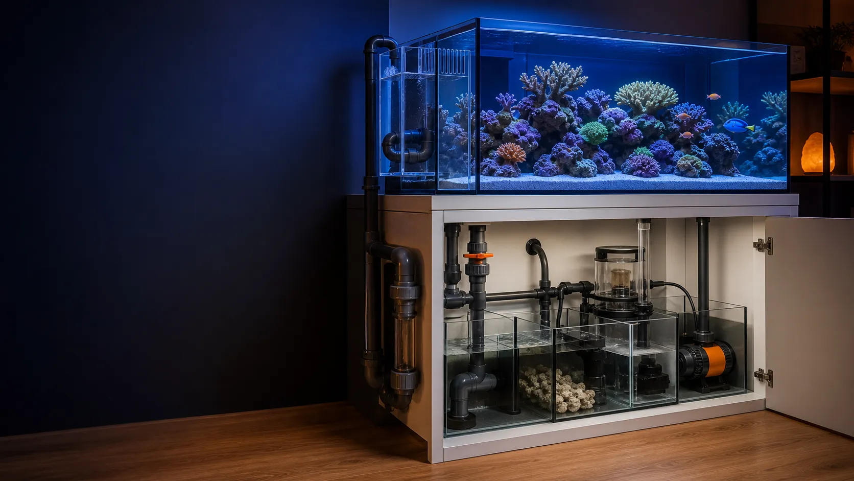

 Published sources
 Product details checked
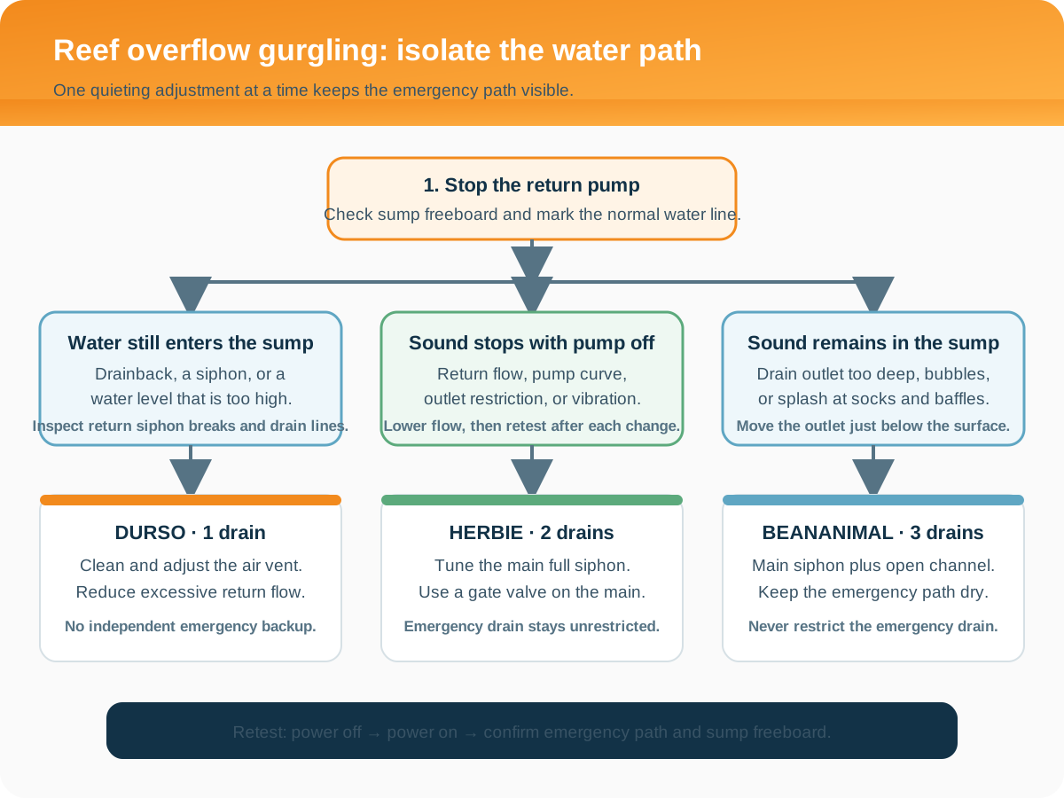
Match the adjustment to the drain: clean and balance the air vent on a Durso; adjust the main full-siphon valve on a Herbie; check the main siphon and vented open channel separately on a BeanAnimal. Keep the emergency drain unrestricted. If the display water is rising toward the rim or the return pump is drawing air, switch off the return pump and resolve the water-level problem before tuning for noise.
A repeating flush, a hiss at the standpipe, a waterfall inside the overflow, and bubbles bursting in the sump have different causes. Find where the sound starts, watch what the water does, and change one thing at a time. A quieter setting is useful only if the tank still drains safely and restarts without help.
If the sound comes from the filter housing or impeller, use our aquarium filter noise guide. The checks below concern the overflow, gravity drains, sump, and return circuit.
Jump to: identify your drain · locate the noise · Durso · Herbie · BeanAnimal · power-off and restart · measure return flow.
Make room for drainback first
When the return pump stops, water from the overflow box and plumbing drains into the sump. The return line can also siphon water backward from the display until air enters the return outlet. The empty space above the sump’s operating water line, called freeboard, must accommodate that water with a margin below the rim.
Before a planned shutdown, have containers ready to remove and retain saltwater if necessary. Keep electrical connections dry and the pump switch within reach. If a flood is already developing, stop the return pump immediately and contain the drainback. Remove excess sump water into a clean container; do not restart until the system has enough room for the next shutdown. Avoid pulling a standpipe out of a full overflow box, because that can release additional water into the sump.
A check valve or a small anti-siphon hole can reduce drainback, but maintenance and a proven sump reserve still matter. Debris can stop a check valve from sealing. Base the reserve on the water that can actually return to the sump, including a backward siphon from the return outlets. The sump-design guidance from gmacreef explains these drainback sources and the limitations of relying on a check valve.
Pause the automatic top-off system while carrying out maintenance or tests that change water levels. Keep circulation pumps running only where they remain safely submerged. A skimmer may need to stay off while the sump water is temporarily high; resume it at its normal operating depth. Red Sea’s REEFER operation manual, English page 9 calls for a power-out test after setup or new sump equipment and warns that excessive water or equipment displacement can cause a flood.
Identify your overflow before adjusting anything
Trace each pipe from its intake to its sump outlet. Count drain paths, not every hole in the aquarium: a return connection brings water back up and provides no emergency drainage. Pipe count helps identify the layout, but two vented standpipes are still two open-channel drains; they do not become a Herbie merely because there are two of them.
An open channel carries water with an air passage. A full siphon carries water through a filled pipe after the trapped air has escaped. Their air requirements are different.
| System | Normal drainage | Where air belongs | Adjustment and backup |
|---|---|---|---|
| Single Durso | One vented standpipe carries water and air | Through the cap vent, above the overflow water line | Adjust the vent and return flow. A single drain has no independent emergency path. |
| Herbie | A submerged main drain runs as a full siphon | Keep air out of the main siphon; keep the higher emergency intake available | Tune the main siphon valve. The emergency remains unrestricted. |
| BeanAnimal | A full siphon carries most water; a vented open channel carries a small remainder | The open channel has an airline; the main siphon remains sealed against air entry | Tune the main siphon valve. Preserve the open-channel vent arrangement and a separate dry emergency. |
| Hang-on-back U-tube overflow | A water-filled U-tube transfers water over the tank rim to an external box | Air collecting at the U-tube’s crown threatens the transfer siphon | Follow the specific overflow instructions. Two outlets in the external box do not protect against loss of the shared transfer siphon. |
The original BeanAnimal design uses three standpipes with separate roles. Its vented open channel is a normal operating path; the third standpipe provides emergency drainage. Keep those roles distinct when checking a system with similar-looking elbows or caps.
For a U-tube overflow, reducing the pump excessively can introduce a different problem: water may no longer carry accumulated air through the transfer tube. Aqueon’s ProFlex hang-on overflow manual, English page 6 describes air collecting at the bend and interrupting the siphon. Its assembly instructions apply to the named ProFlex models, but the failure mechanism explains why a U-tube needs its own checks.
Locate the noise while the system is running
Start with observation before touching a valve. Note the return-pump setting, the overflow water line, the sump water line, and which drain outlets carry water. A short video lets you compare the sound and water-level pattern after each change.
Listen near the overflow box, along the drain as it enters the cabinet, and at the sump outlet. Keep your face, hands, and recording device away from splashing water and electrical equipment. Check whether the pipe or pump is touching the cabinet, since vibration can travel to a place that appears to be the source.
| Observation | What to distinguish | First useful check |
|---|---|---|
| Overflow fills, suddenly empties, then refills with a flush | Durso air imbalance or a full siphon repeatedly losing its water seal | Identify the drain type, inspect its intake, and use the relevant vent or siphon checks below. |
| Hiss or slurp at the top of a Durso | Air entering through its intended vent versus a vortex at the water intake | Clean the vent and check the intake water level. |
| Steady waterfall behind the overflow teeth | Water falling into the box versus noise inside a drain | Check the standpipe’s specified operating height and whether a fitted cover is seated correctly. |
| Bursts of bubbles or a pulsing outlet in the sump | Air carried by an open channel versus air that has not cleared from a main siphon | Check outlet depth, pipe routing, and whether the main siphon has settled. |
| Water continues through the emergency after startup has settled | A change from normal operation, main-drain restriction, or excessive return flow | Keep the emergency open; inspect the main path before further adjustment. |
| A hum or rattle changes when the plumbing is gently supported | Vibration transmitted through rigid pipe, glass, or the cabinet | Check supports and pump mounting without stressing a bulkhead. |
On a drilled system with a controllable pump, lower the return setting one step and watch the response. Leave the drain valve unchanged during this comparison. A lower rate that stops the cycle shows that flow affects the symptom; it does not prove that the drain is clear or that the backup can handle the original rate. Waterbox’s overflow troubleshooting instructions also recommend checking return flow against drain size when main-valve adjustment does not resolve the noise.
Stopping the return pump is a useful second observation once drainback is under control. Most flow-dependent sounds stop because water is no longer being pumped into the display. Noise during the remaining drainback can still come from the overflow or sump. Pump-off silence alone does not distinguish pump vibration from drain noise. Compare the sound’s location and water-level behavior before shutdown, during drainback, and after restart.
How to quiet a Durso overflow
A Durso needs a working air vent. Sealing that vent to obtain silence changes the drain’s behavior and can make it repeatedly fill as a siphon, empty the overflow, and gulp air when the inlet becomes exposed.
Restore the intended air supply
Switch off the return pump, allow drainback to settle, and inspect the cap vent or airline for salt deposits, dust, or a blockage. Clean it back to its existing size first. Refit the cap and airline securely, then restart under observation.
If the water still rises and falls, compare the vent with the standpipe’s instructions. Richard Durso’s standpipe construction guide connects rapid level fluctuation with insufficient air admission and explains that an oversized hole can also raise the operating level. There is no universal drill size that makes every flow rate and pipe layout quiet.
For a DIY cap that needs adjustment, work on a removable part with the pump off and keep a replacement available. Increase air admission gradually according to the design guidance, then test again. Avoid drilling an installed cap over a running aquarium. If the hole has become too large, replace the cap rather than trying to compensate by restricting the drain below it.
An air valve gives finer control without repeatedly drilling the cap. It is an airline valve, not a water-flow valve on the drain pipe. Durso’s air-valve modification describes that arrangement and the cleaning it needs as deposits accumulate. Keep the vent accessible, and do not let the airline’s open end become submerged.
Check intake height, pipe route, and return rate
Look for a visible whirlpool at the intake. Check that the standpipe is seated at its intended height and the intake is clear. Raising the pipe indiscriminately can reduce a waterfall while leaving insufficient room for abnormal water levels. Use the overflow’s intended geometry and retain clearance below the tank rim.
The Durso construction guide shows the operating level around the elbow in its own layout. That drawing is a better reference than trying to hold every overflow at the highest possible level. For a rear-drilled installation, Durso’s external-overflow guidance also explains why a surrounding overflow chamber limits how far the display can drain during a power outage.
Check for flexible hose that sags into an air-trapping route, a clogged intake, and a drain outlet that has been pushed deeper into the sump. Correct an obvious obstruction with the pump off. Then compare normal operation at a lower return setting. If the vent is clear and the level still cycles at the desired rate, reduce return flow or have the drain layout assessed; do not force a single Durso into a valved full siphon without a separate backup.
How to tune a Herbie overflow
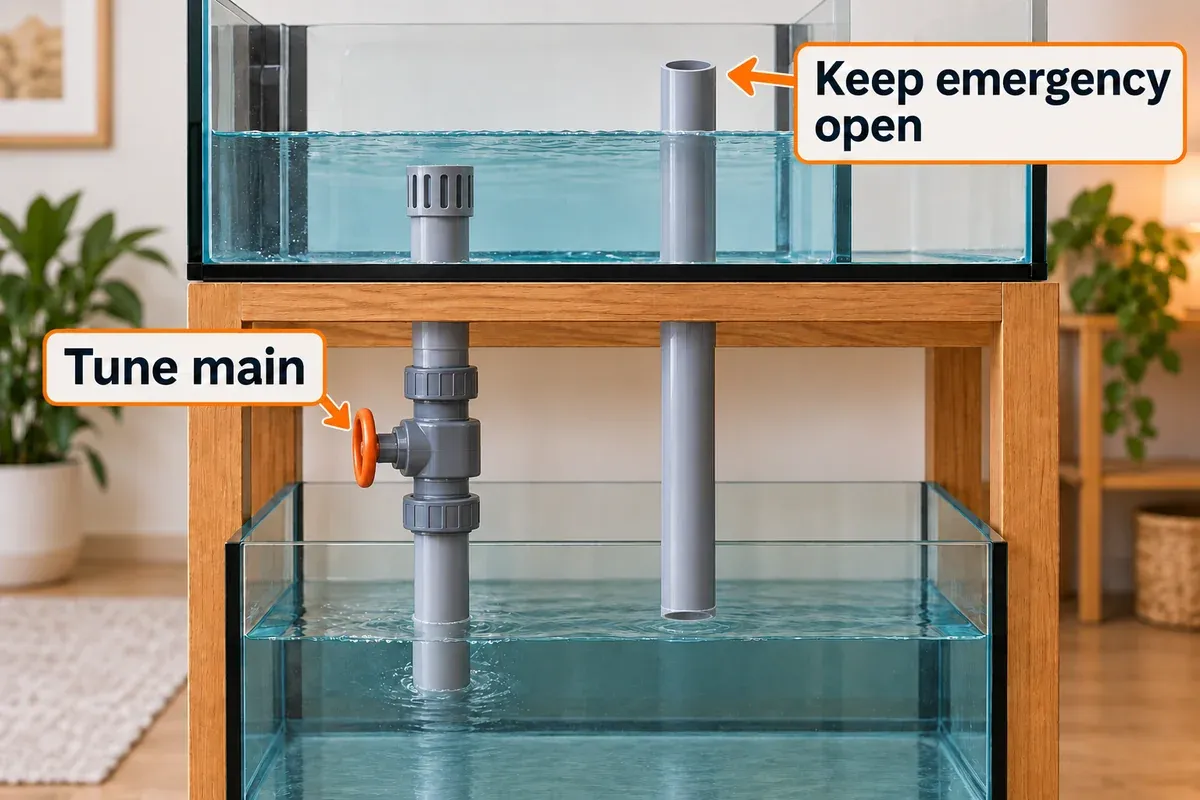
A Herbie uses a submerged full siphon and a higher emergency drain. The main siphon must clear its trapped air and remain submerged during normal operation. The emergency needs an independent, open route to the sump.
Keep the pump at one steady setting while adjusting the main valve. Otherwise, changing both incoming flow and drain restriction makes it difficult to tell why the level moved.
Tune the main siphon in small steps
- Inspect before adjusting. With the return pump off, check the main intake, strainer, valve, and pipe route for obstructions. Identify the emergency intake and trace its outlet.
- Choose a conservative return setting. Restore the normal sump operating level. Open the main siphon valve for initial commissioning as directed by the system manual, and start the pump under observation.
- Let the initial air clear. A fully open main drain may pull the overflow level below its intake and gulp air. That shows that it is draining faster than water is arriving.
- Close only the main valve a little. This reduces main-drain flow and raises the overflow level. Wait for the level to settle before making another change.
- Keep the main intake submerged. Aim for a steady water line in the range specified for the overflow, with reserve below the emergency intake in a dry-emergency layout.
- Reverse the change if the level keeps rising. Open the main valve slightly, reduce the return setting, or stop the pump if water approaches an unsafe height. Leave the emergency unrestricted throughout.
- Record the stable position and test restart. Note the pump setting, valve position, and normal water line. A quiet operating level is only part of the check.
Waterbox’s main-drain adjustment guidance calls for small changes with several minutes between them. Use a settled water level as the decision point; a fixed 30-second wait is not a guarantee that your plumbing has finished responding.
For the REEFER valve arrangement covered by Red Sea’s cleaning and adjustment guide, the operating target is about 1 cm below the emergency downpipe, with a few minutes after each adjustment. That is a model-specific reference, not a universal height for DIY Herbie systems or every REEFER generation. Follow the instructions for your exact aquarium and valve before taking either apart.
The two-drain example below separates the adjustment from the backup path. A quiet main drain is useful only while the emergency remains available.
Interpret water in the emergency correctly
A newly engaged emergency during otherwise steady operation deserves attention. First inspect the main intake and valve for deposits or debris. Also check whether a recently cleaned pump, a changed manifold setting, or a controller program has increased the return flow. Repeated valve adjustment can conceal a progressive blockage.
Some Herbie layouts use a very small trickle through the second pipe; others reserve it as a dry emergency. The gmacreef discussion of dry emergencies and trickle operation explains the balance tradeoff and the need to preserve backup capacity. Use the operating condition specified for your system. A new, substantial, or increasing flow down the second drain is not something to silence by closing that drain.
During restart, the emergency may briefly carry water while the main siphon clears air. Once the siphon settles, drainage should return to the system’s normal pattern. Persistent emergency flow, a rising display level, or repeated flushing requires investigation.
Use a valve that can hold a fine adjustment
For main-siphon tuning, a screw-operated gate valve provides small, repeatable changes. The gmacreef Herbie guide’s valve section distinguishes that use from the coarser adjustment of many ball valves. Match the fitting standard, pipe size, saltwater compatibility, and service access; a valve described simply as a “gate valve” does not establish how precisely it can be adjusted.
Keep a full siphon sealed against unintended air entry. Adding a Durso-style vent to its cap works against the intended siphon. If a system already includes a service isolation valve on a backup pipe, keep it fully open and protected against accidental movement. It must not become a noise-control setting.
How to check a BeanAnimal overflow
A BeanAnimal has a main full siphon, a vented open channel, and a separate emergency. The small residual flow through the open channel is intentional. If you treat that pipe as the emergency and try to make it dry, you remove the system’s normal way of accommodating flow variation.
Check the pipes separately:
- Main siphon: inspect its submerged intake, sealed cap, tuning valve, and outlet. Air entering here prevents a stable full siphon.
- Open channel: check that its airline is clear and retained at the intended height. A small flow here is normal; a sudden increase can indicate a change in the main siphon or return flow.
- Emergency: inspect its intake and independent route. It should be dry after normal operation settles and remain available without a throttling restriction.
In the original BeanAnimal design, the open-channel airline ends at the high-water position. Rising water covers that opening and lets the open channel become a siphon for additional drainage. Moving the airline outside the box, leaving it too low, or plugging it to stop a hiss changes that safety behavior. Restore the designed arrangement before adjusting the main valve.
If the open channel carries enough water to gurgle, inspect the main siphon and compare the return setting with the stable baseline. Tune the main siphon gradually while allowing a small remainder through the open channel. Do not close the open channel to force all flow through the main pipe, and do not throttle the emergency to hide the sound.
All three outlets need suitable discharge conditions. A deeply submerged outlet or an air-trapping pipe route can interfere with startup. The original arrangement places the outlets just below the sump surface; use the installed overflow’s instructions for the actual depth. Finish with the shutdown and restart observations below.
Test power-off drainback and restart
Carry out this check with enough sump reserve, clear drain paths, and immediate access to the pump switch. For new plumbing, commission and leak-test before adding livestock. On an established reef, retain safe in-tank circulation and keep the interruption supervised.
1. Record steady operation
Mark or photograph the display level, overflow level, and sump operating level. Note the return controller setting and main-valve position. Record which pipes carry water. This gives you a reference for the restarted system.
2. Switch off the return pump and watch the water routes
Leave the drain outlets open. Watch the overflow empty to its resting level, then watch the return outlets for backward siphoning. A gurgle as the return siphon breaks can be normal during shutdown; it should end when drainback ends.
Follow both the display and sump levels until they stop changing. Keep a clean container ready to remove water if the sump approaches an unsafe level. Do not confuse slow drainback with a finished test.
3. Check the final sump level
The resting level must remain below the rim with room for uncertainty. Check that submerged equipment is still positioned appropriately and no fitting is leaking. If the reserve is inadequate, lower the operating water volume or correct the return-outlet and sump layout before repeating the test. Keep heaters and pump intakes within their specified immersion limits.
A clean anti-siphon hole may stop the return siphon earlier, but a blocked hole can change the result. Assess how much water can drain until the return outlet itself admits air. Use sufficient sump capacity for that condition rather than treating a small hole as the only flood protection.
4. Restart without touching the drain adjustment
Before restarting, confirm that the pump chamber contains enough water. Start the pump at its recorded setting, keep the ATO paused, and watch both the display and overflow. The sump pump chamber will fall as the display refills; stop immediately if the pump inlet begins drawing air.
On a full-siphon system, watch the main outlet expel air and the overflow settle. gmacreef’s Herbie starting-and-stopping explanation describes temporary emergency flow during that transition. Do not keep turning the main valve in response to every startup bubble.
5. Decide whether the restart passes
| Restart observation | Interpretation and next step |
|---|---|
| Levels return to their recorded positions; the main siphon clears air; the normal drainage pattern resumes | The observed restart passed. Restore the ATO and skimmer once normal water levels are established. |
| The emergency briefly carries water, then returns to its normal condition | This can be part of siphon startup. Judge the settled behavior and retain clearance below the rim throughout. |
| The emergency keeps carrying a substantial flow, or the display continues rising | Stop the pump before an unsafe level. Inspect the main path, outlet depth, vent arrangement where applicable, and return setting. |
| The main drain repeatedly gulps air or starts and breaks its siphon | Check intake submergence, air leaks, trapped-air routes, and the system-specific adjustment. |
| The pump chamber empties or the pump draws air | Stop the pump. Recheck operating volume, compartment layout, and any restriction between sump chambers. |
| A U-tube needs manual priming after every shutdown | The transfer siphon is not reliably retained. Use that overflow’s setup instructions and resolve the cause before unattended operation. |
Repeat after a plumbing, pump, outlet-height, or controller change. Test the operating modes that can restart automatically, including feed-mode recovery if it changes pump behavior. A pass at one deliberately reduced setting does not establish safety at a higher startup setting.
Check backup capacity separately
A shutdown test checks sump reserve; a restart test checks recovery. Neither proves that the emergency can carry the return flow when the main drain is blocked.
For a correctly assembled multi-drain system, follow its commissioning instructions for a supervised backup-capacity test. Prefer doing this before livestock are present. Confirm that the backup path and sump destination are clear, mark the normal main-valve setting, and have the pump switch immediately available. Where the design permits testing by closing the main siphon valve, introduce the restriction gradually and abort if water keeps rising instead of reaching a safe, stable level. Restore the main valve and normal drainage afterward. The Herbie commissioning guide explicitly separates testing emergency capacity from checking sump drainback.
On a BeanAnimal, restricting the main alone tests the available secondary paths together. It does not independently establish the dry emergency’s capacity. Use the overflow manufacturer’s procedure to verify that path; do not improvise by blocking several drains on an occupied tank. Never restrict the only drain on a single-Durso system as a test.
The tested return setting must cover the highest setting the controller can use automatically. If a higher mode has not been checked, limit the controller to the verified operating range. Get an aquarium installer to assess the plumbing if the backup cannot stabilize the water level or the intended flow remains uncertain.
Measure the return flow your overflow actually receives
The pump’s maximum GPH is usually a zero-head figure. Lift, pipe friction, fittings, valves, sensors, and the return nozzle reduce installed flow. The Current USA eFlux pump data and flow chart show why maximum flow and maximum head are different ends of a pump’s operating range.
Measure the water reaching the display. A manifold branch that returns to a reactor or refugium in the sump is not display return flow. If there are two display outlets, account for both. After levels have stabilized, total display return and total overflow drainage should balance; measuring only a BeanAnimal’s main siphon omits the open-channel flow.
Use an installed flow sensor where possible
Choose a sensor whose measuring range includes the expected flow and whose connections match the actual plumbing. Fit it according to its instructions for direction, pipe position, straight sections, and keeping its electronics dry. A sensor upstream of a sump-returning manifold branch reports more than the display receives; measure downstream of that branch or measure and account for each branch separately.
For reference, Neptune’s flow-sensor overview describes the FS-100 as a 1-inch inline sensor with a 150–1,500 GPH range, connected through an FMM. Those limits belong to that sensor, not to every flow meter.
Record the reading at the normal sump level and steady pump setting. Recheck after cleaning the pump or altering the return plumbing. A pump setting of 50% should not be assumed to deliver half the installed GPH; use the reading or a performance curve for that setting.
Use a timed collection only when the setup permits it
A marked container and stopwatch can give a useful check during commissioning, but moving an outlet changes the conditions you are measuring. A short hose discharging beside the sump measures a different head from the installed return at the display.
Use this method only if you can safely collect the complete outlet flow while preserving its usual height and discharge conditions. Keep the normal drain and emergency routes available. Plan the container capacity in advance and stop before either the container fills or the pump chamber falls near the pump’s minimum water level. Do not pull apart live plumbing or divert a drain into a small bucket just to obtain a number.
- Confirm a stable pump setting and sump water level. Use a container with a known volume scale.
- Collect water over a timed interval at the intended return outlet, only where its original conditions can be maintained. Account for every display return outlet.
- Record collected volume and elapsed seconds. If the pump chamber level changes materially, treat the reading as an approximation of changing flow, not a steady operating measurement.
- Restore normal circulation, return the retained clean saltwater, and repeat at the original water level if the setup remains safe.
- Compare repeated readings. If the setup cannot preserve the discharge conditions or safely contain the flow, use an inline sensor instead.
US GPH = collected US gallons × 3,600 / elapsed seconds
L/h    = collected liters × 3,600 / elapsed seconds
L/h    = US GPH × 3.78541
Calculation example, using assumed values: collecting 2 US gallons in 12 seconds gives 2 × 3,600 / 12 = 600 US GPH, or about 2,271 L/h. This is a unit-conversion example, not a measurement from a reef system. UK imperial gallons require a different conversion.
Use the reef return pump size calculator to estimate head losses and compare a pump curve at the planned operating point. Use an installed measurement and the safety tests above to verify the assembled system. Coral circulation inside the display is a separate requirement, usually addressed with circulation pumps and their placement; increasing sump turnover is not a substitute for that flow plan.
Keep a short troubleshooting record
Copy this table into your maintenance notes. Record observations after the system has settled; do not change the pump and main valve together in one comparison.
| Check | Pump setting / measured flow | Overflow and sump levels | Which drains carry water? | Sound and result |
|---|---|---|---|---|
| Before adjustment | Fill in | Fill in | Fill in | Fill in |
| After one change | Fill in | Fill in | Fill in | Fill in |
| Pump off, drainback complete | Pump off | Fill in resting levels | Record when flow stops | Record remaining noise |
| Restart, fully settled | Fill in | Compare with baseline | Compare with normal pattern | Pass or describe the unresolved fault |
If a clear Durso becomes stable at a lower measured return rate, retain that operating point while reviewing drain capacity. If a Herbie or BeanAnimal still surges at modest flow, inspect air entry, outlet depth, and routing before buying a larger pump or another silencer.
Quiet the sump without reducing drainage capacity
Start at the drain outlet. A main siphon that repeatedly spits air is still a siphon problem even when the sound is loudest in the sump. Once drainage is stable, separate outlet noise from a waterfall over a baffle, a clogged sock, or pump vibration.
For the Herbie layout described by gmacreef’s drain-outlet guidance, the siphon outlet is just submerged, less than 1 inch / about 25 mm, in a chamber with a steady water level. A deeper outlet makes clearing air harder. Treat that as a design reference; an integrated drain chamber or roller filter may require its own manufacturer’s connection depth.
Check the following without altering the emergency’s intake or capacity:
- Secure the outlet so that cleaning cannot push it farther underwater. Allow access for inspection.
- Clean a filter sock or replace blocked mechanical media. Retain the sump’s intended bypass route if media clogs.
- Keep an emergency outlet free of a restrictive sock, packed foam, a makeshift cap, or a submerged silencer that has not been approved for that drain layout.
- Inspect baffles for trapped debris and an unusually large water drop. Raising the entire sump level to silence that drop also consumes drainback reserve.
- Check pump mounts and pipe supports. Support plumbing independently so it does not load a bulkhead or transmit vibration into the cabinet.
Red Sea’s REEFER water-management description, English page 8 describes filter-bag bypass and bubble separation as parts of the sump layout. Those functions should remain available when adding noise-control accessories. If a changing sump level also makes the skimmer overflow, follow the protein skimmer troubleshooting guide for that separate symptom.
When a replacement component helps
Cleaning, restoring the intended outlet position, and selecting a stable return setting may solve the noise without a purchase. A component is useful when it addresses a confirmed limitation: missing drain paths in a new build, inadequate pump control, or a sump layout that repeatedly creates splash and bubbles.
Components for specific overflow and sump problems
-
FijiCube Low Profile External Overflow Box (800 GPH)
Fiji Cube
A slim external acrylic overflow with a detachable skimmer box, front and back lid covers, an included drilling template and diamond hole saw, and emergency-drain plumbing components.
- 800 GPH rated flow class
- Front and back lid covers for quieter water flow
- Two 1 in drain bulkheads for a Herbie layout
- Use case
- A drilled reef build needing a compact external overflow with a quieter Herbie-style path
-
ESHOPPS PF-1000 Power Flow Overflow Box
ESHOPPS
A hang-on-back U-tube overflow with a slimmer internal pre-filter box, recessed external cover, dual intake, and two 1-inch bulkhead connections.
- 1,000 GPH maximum listed flow
- Two 1-inch bulkhead connections
- Dual U-tube intake and recessed cover
- Use case
- Adding a sump to an undrilled aquarium without cutting the tank
-
Reef Octopus VarioS-4 Controllable DC Circulation Pump
Reef Octopus
A controllable 24V DC return pump with a strong published delivery-height rating, float-switch input, and 0-10V control.
- 1,050 GPH maximum flow
- 14.7 ft maximum head
- 0-10V and float-switch inputs
- Use case
- Higher-head return lines that need controllable reserve
-
Current USA eFlux DC Flow Pump 1900 GPH
Current USA
A controllable 24V DC pump for submersible or external use with a 380–1,900 GPH published range and LOOP Hub control.
- 380–1,900 GPH flow range
- 14.75 ft maximum head
- 1.5 in pump connections with 0.75 in and 1 in outlets
- Use case
- Larger systems with a broad control range and higher-head plumbing
-
FijiCube Sump Baffle Kit for 20 Gallon Long DIY Aqueon Sump
Fiji Cube
A cast-acrylic DIY kit for a 20-gallon-long Aqueon tank with filter-sock holders, sock silencers, an adjustable water-height baffle, bubble-trap baffle, media trays, and bio-foams.
- Adjustable 4.5–8 in water-height baffle
- Two filter-sock silencers and two 200-micron socks
- Bubble-trap baffle plus media trays
- Use case
- Building a controlled 20-gallon-long sump with quieter sock intake and adjustable baffle height
Match drain count, tank construction, fittings, pump flow at head, and sump dimensions. Preserve an unrestricted backup path.
FijiCube 800 GPH external overflow: a two-drain drilled build
The FijiCube 800 GPH external overflow has two 1-inch drain bulkheads, as shown in the manufacturer’s specification chart. That permits a Herbie arrangement with a main siphon and emergency. This 800-GPH version does not provide the three independent drain connections required for BeanAnimal.
Its removable inner skimmer box gives access for cleaning; front and rear covers reduce exposed water-flow noise. The kit includes a drilling template, diamond hole saw, bulkheads, gaskets, and emergency-drain PVC. The 800-GPH rating identifies its nominal flow class, not a measured quiet-flow limit or proof of emergency capacity in your installation.
Choose it for a planned drilled build with suitable access behind the tank. Verify that the panel may be drilled, the required hole positions and tank thickness fit, and the plumbing can be routed independently. Do not drill tempered glass. Drilling tools in the kit do not establish that your aquarium panel is suitable. Leak-test and carry out the capacity and restart checks before livestock are present.
Check current price on Amazon →ESHOPPS PF-1000: a U-tube route for an undrilled aquarium
The ESHOPPS PF-1000 uses a hang-on-back U-tube transfer, dual intake, and 1-inch bulkhead fittings. ESHOPPS specifies a 1,000-GPH maximum flow and aquarium guidance up to 150 gallons. Its slim internal box and recessed external cover address space and splash, but the whole system still depends on retaining the transfer siphon.
Use it where drilling is unsuitable and the siphon can be inspected and maintained. Check both tubes for accumulated air and confirm power-off recovery at the intended return rate. Two drains from the outer box do not provide an independent path across the tank rim if the transfer siphon is lost. A multi-drain drilled system is a different design choice.
Check current price on Amazon →Controllable return pumps: VarioS-4 and eFlux 1900
A replacement pump helps when the existing unit lacks a safe way to set the required flow or cannot supply it at the actual head. Select the pump from its curve, connection sizes, and usable adjustment range.
The Reef Octopus VarioS-4 data give a maximum flow of 4,000 L/h, roughly 1,050 US GPH, and a maximum head of 4.5 m / 14.7 ft. Five speed settings, 0–10 V control, feed modes, and a float-switch input offer repeatable control. Check whether the chosen speed produces a stable return rate in your installation; maximum flow and maximum head are not simultaneous performance values.
Check current price on Amazon →The Current USA eFlux 1900, model 6010, has a 380–1,900 GPH published range, 14.75 ft maximum head, a LOOP Hub controller, and soft start. Its 1.5-inch threaded pump connections and supplied outlet adapters need a compatible plumbing transition. Choose it when its curve and control range fit the system; the larger headline flow is not a reason to increase an already stable overflow rate.
Check current price on Amazon →For a valve replacement, select a serviceable screw-operated main-siphon valve in the exact pipe size. Pipe labels, metric fittings, slip sockets, and threaded connections are not interchangeable. Keep the emergency route fully open regardless of which pump or valve you choose.
FijiCube 20-gallon-long baffle kit: sump splash and layout
The FijiCube 20-gallon-long sump baffle kit includes filter-sock holders and silencers, media trays, a bubble-trap baffle, and an adjustable 4.5–8-inch water-height section. Choose the Aqueon 20G Long version for the named Aqueon tank; the separately offered Marineland/Tetra version is a different fit.
It can help organize sump equipment and reduce sock-entry splash. It cannot repair an air-bound siphon or add capacity to an undersized emergency. Measure the tank’s interior, skimmer footprint, pump chamber, and available drainback reserve before bonding baffles. The glass tank, skimmer, silicone, and assembly adhesive need separate planning.
Check current price on Amazon →Maintenance that keeps the operating point stable
During routine tank checks, look at the overflow water line and identify any new flow through a backup pipe. Check strainers, overflow teeth, accessible vents, and U-tubes where fitted. A changed sound should prompt inspection even if the maintenance calendar says cleaning is not due.
Clean deposits using the relevant component instructions. For a Durso, include the cap vent or airline valve. For a Herbie or BeanAnimal, include the main intake and valve while protecting the emergency from debris. Keep the BeanAnimal open-channel airline fixed at its intended height. Inspect filter socks and retain access to their bypass route.
After pump cleaning, compare the actual return flow or overflow level with your record; restored pump performance can alter a previously balanced system. Recheck after changing manifold branches, moving sump outlets, replacing media, or changing controller modes. Carry out the supervised shutdown and restart test after any change that affects water routing or volume.
Common overflow questions
Why did the gurgling start after a water change?
Compare the new sump operating level and drain-outlet depth with the previous ones. Check whether an outlet moved, a strainer collected debris, or the pump and valve settings changed. A higher sump level can submerge outlets more deeply. Pause the ATO during the check, restore the intended water levels, and use the relevant drain-specific procedure.
Should a Herbie emergency always be dry?
Use the condition specified for the system: a dry emergency in a dry-emergency layout, or the small trickle permitted by a design that explicitly uses it. New or increasing flow needs investigation. A brief startup flow is different from a backup carrying substantial water after the main siphon has settled. Never throttle the emergency to obtain silence.
Why does my BeanAnimal’s second pipe carry water?
The vented open channel normally carries the small remainder that the main siphon does not take. The third pipe is the emergency. Confirm those roles by tracing the plumbing; substantial new flow in the second pipe can indicate reduced main-siphon performance or increased return flow.
Can I add an airline to any noisy drain?
No. A Durso vent admits air during normal operation. A BeanAnimal open-channel airline also participates in its high-water response. A main full siphon must avoid air entry. Adding or relocating an airline without identifying the drain can change both its operating capacity and its restart behavior.
Is the emergency gurgling during restart a fault?
It can briefly carry water while the main siphon clears air. Watch the direction of the water-level change and the settled drainage pattern. Stop if water approaches the rim or the pump draws air. A backup that remains heavily loaded after startup, or a siphon that repeatedly fails to settle, needs attention.
Should I submerge the drain farther to stop splashing?
Use the depth specified for that drain and sump. A deeply submerged outlet can make clearing air harder. Check the actual water line and secure the outlet before adding a silencer. Preserve the emergency’s discharge capacity and enough sump reserve for shutdown.
Does lower return flow harm coral circulation?
Return flow through the sump and circulation inside the display serve different purposes. Check the needs of the livestock and filtration before changing either. If the overflow cannot handle the intended return rate safely, solve that limitation and provide the required in-tank flow through an appropriate circulation plan.
Sources and further reading
- Richard Durso: standpipe construction and air-hole behavior
- Richard Durso: air-valve modification
- Richard Durso: external-overflow adaptations
- BeanAnimal: original three-standpipe design
- gmacreef: Herbie plumbing, valve selection, restart, and commissioning
- gmacreef: dry emergency versus trickle operation
- gmacreef: sump design and drainback
- Waterbox: overflow noise troubleshooting
- Red Sea: REEFER downflow-valve cleaning and adjustment
- Red Sea: REEFER series operation manual
- Aqueon: ProFlex hang-on overflow instructions
- Neptune Systems: flow-sensor overview
- FijiCube: 800 GPH overflow and specification chart
- ESHOPPS: PF-1000 overflow specifications
- Reef Octopus: VarioS pump technical data
- Current USA: eFlux 1900 specifications and flow chart
- FijiCube: 20-gallon-long sump baffle kit