

 Published sources
 Product details checked
Choose a reef return pump that delivers your target flow at the total head of your installed return line. For example, the 150-US-gallon setup below needs 600 GPH at about 10.2 ft of head. A pump labeled 600 GPH at zero head cannot meet that requirement.
Begin with the water volume you want to circulate through the sump, choose a return turnover, and measure the complete pipe route. The calculator gives you a flow-and-head pair to compare with a manufacturer’s pump curve. It does not predict the output of a particular pump, and it does not size the wavemakers that circulate water around your corals.
On This Page
- Choose your return turnover
- Measure the return line
- Use the calculator
- Understand the calculation and its limits
- Work through US and metric examples
- Compare pumps at the calculated head
- Measure installed flow
- Check shutdown, restart, and maintenance
Choose Your Return Turnover
Return turnover describes how many times per hour a stated water volume passes through the sump-return circuit. At 4× turnover, 75 US gallons of operating water needs 300 US gallons per hour at the display. Keep the volume basis consistent when comparing that target with a measured result.
For many reef systems, 2–5× operating volume per hour is a useful starting range. Bulk Reef Supply’s return-pump sizing guide describes that range after plumbing losses for systems using modern filtration. Treat it as a planning range, not a minimum requirement for every reef. The aquarium and overflow instructions, your filtration layout, and the flow requirements of connected equipment determine the final setting.
Use the water that actually circulates during normal operation. A tank’s advertised capacity includes space occupied by rock and substrate and may describe a fill level above the working waterline. A sump also runs partly empty to hold drainback. If you include the sump’s operating water in your volume estimate, include that same volume when you calculate actual turnover later.
Sump turnover and coral circulation serve different jobs
The return pump moves water between the display and filtration. Wavemakers create flow within the display, where rockwork, coral placement, and pump direction affect the pattern. Adding up the advertised output of all those pumps does not tell you how much water passes through the sump.
Set return flow around the filtration circuit. Then plan display circulation for the animals and aquascape. Trying to obtain all coral flow from the return pump can force unnecessary water through the drains and a small sump.
Let the most restrictive part of the system set the limit
Before increasing turnover, identify what has to process the water:
| Part of the system | What to check before setting return flow |
|---|---|
| Overflow and drains | The exact overflow’s flow limit, required drain arrangement, and reliable restart behavior |
| Mechanical filtration | Whether water passes through the media as intended or bypasses it when resistance rises |
| Return chamber | Whether the intake remains submerged and free of persistent air at the normal operating level |
| Skimmer chamber | The skimmer’s required water depth and whether that depth remains stable |
| UV, chiller, or reactor | The specific unit’s permitted or required flow through its own branch |
A skimmer’s own pump processes water inside the skimmer; sump turnover does not automatically equal skimmer throughput. If the skimmer cup overfills after a change to sump flow or water level, use the protein skimmer overflowing guide to distinguish depth, air intake, and foaming causes before replacing equipment.
An overflow’s maximum rating is a limit, not a flow target. Leave room to operate and restart reliably. If your drain repeatedly gulps air, surges, or fails to settle, follow the reef overflow gurgling checks for the installed drain type before turning the pump up further.
Measure the Return Line Before You Calculate
Make a simple sketch from the pump intake to the display return. Mark the main pipe size, every diameter change, elbows, valves, unions, and any equipment connected to the line. Measurements from that sketch are more useful than estimating losses from tank height alone.
Measure vertical rise from the working water level
For the usual sump return with an outlet near the display surface, measure the vertical distance from the sump’s normal operating water level to the outlet. The cabinet floor and the bottom of a submerged pump are not the starting level. Check the lower operating water level separately if evaporation can appreciably lower the return chamber.
The calculator is intended for a conventional open sump and return near the display waterline. A deeply submerged outlet, a pressurized destination, or an unusual installation needs the appropriate static-head assessment; outlet elevation alone may not capture the pressure at discharge.
Measure all straight pipe, including the vertical sections
Trace the actual route of the pipe or hose. Include vertical, horizontal, and diagonal sections, detours behind the cabinet, and any straight section below the sump waterline. Count elbows in their separate fields.
For 4 ft of vertical pipe plus 20 ft of horizontal pipe, enter:
- Vertical rise: 4 ft
- Total straight pipe length: 24 ft
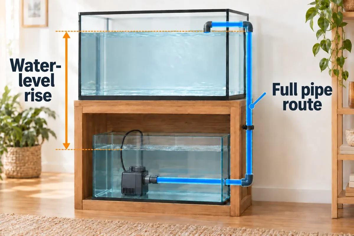
Those entries describe different effects. Vertical rise is the lift between water levels. Total pipe length determines friction along the route. Including the vertical pipe in the length field does not count static lift twice.
The two measurements highlighted below describe different effects. The rise starts at the working water level; the pipe-length measurement follows the full route, including its vertical sections.
Check inside diameter, not just the size printed on the fitting
Nominal pipe size identifies a pipe system; it is not a direct measurement of the open passage. A hose labeled 1 inch, metric PVC, Schedule 40 PVC, and Schedule 80 PVC do not necessarily have the same inside diameter.
The calculator uses these approximate Schedule 40 PVC inside diameters. Compare your actual pipe specification with the Charlotte Pipe plastics technical manual, which provides pipe dimensions and friction information.
| Nominal Schedule 40 PVC size | Inside diameter used | Metric equivalent of that inside diameter |
|---|---|---|
| 3/4 in | 0.824 in | 20.93 mm |
| 1 in | 1.049 in | 26.64 mm |
| 1 1/4 in | 1.380 in | 35.05 mm |
| 1 1/2 in | 1.610 in | 40.89 mm |
Do not choose a dropdown option because its nominal number looks close to the outside diameter of a metric pipe. If the actual inside diameter differs materially, use a calculation that accepts that diameter. The dropdown cannot model arbitrary hose sizes or several diameters in series.
Record restrictions at the intended flow
The added-head field covers losses beyond the straight pipe and the elbows already counted: valves, reducers, sensors, nozzles, and equipment in the main return path. Use component loss data at your target flow where available.
The default 1 ft of added head is an allowance, not a measured total for every reef. An almost closed valve or a restrictive device may add much more. If a loss is unknown, compare plausible allowances to see whether your pump choice depends heavily on that uncertainty. Keep it marked as an estimate until the installed flow is checked.
Do not enter a UV unit’s maximum operating pressure as its pressure loss. Those are different specifications. Likewise, a chiller’s recommended L/h range describes water throughput, not the head it adds. If cooling performance depends on that circuit, use the aquarium chiller sizing guide alongside the exact chiller instructions.
Reef Return Pump Size Calculator
Enter your operating volume in US gallons, heights and lengths in feet, and the appropriate Schedule 40 pipe option. All required numbers must fall within the displayed field limits and steps. Total straight pipe length must be at least the vertical rise.
Interactive sizing tool
Estimate real return flow after plumbing losses
Enter the operating water volume, target turnover, and the return-line geometry. The result is the operating point to look for on a pump curve—not the pump's zero-head box rating.
Your pump-curve target
Enter your plumbing details to see the estimated operating point.
Calculation method: Hazen–Williams at C = 150 for smooth PVC, using the full pipe length plus 30 inside diameters per 90° elbow and 16 per 45° elbow. These elbow allowances are approximations. One constant-diameter, unbranched return line is assumed; all losses are in feet of head. A manufacturer's pump curve, overflow limit, and an inline flow measurement take priority over this estimate.
Read the result as: “The pump must supply this GPH at this many feet of head.” The friction portion helps you judge whether the pipe route is causing a substantial part of the load. The calculator has no pump-model input, so the target GPH is a requirement you selected, not a prediction that every shortlisted pump will achieve it.
If a required value is blank or invalid, correct the named field before using the result. Do not treat a previous result as valid for a different, incomplete set of measurements.
Using measurements in liters and meters
Convert before entering values; the form uses US units. US gallons and Imperial gallons are different units. For this calculator:
US gallons = liters / 3.785411784
Feet = meters / 0.3048
Inches = millimeters / 25.4
L/h = US GPH × 3.785411784
Meters of head = feet of head × 0.3048
The volume field accepts whole US gallons and the height and length fields accept tenths of a foot. Round your converted entries to those steps and keep the original measurements in your notes. The 400-liter worked example shows the effect of that rounding. Do not change a pipe’s nominal label into millimeters and assume you have found its inside diameter.
How the Head-Loss Calculation Works
The sizing process begins with two quantities:
Target return GPH = operating water volume × desired return turnover
Total dynamic head = static rise + pipe and fitting friction + other losses
Head expresses the pump’s required energy per unit weight of water as an equivalent height. Feet of head describes resistance as well as elevation. A horizontal line can have substantial friction head even though it adds no vertical lift.
The calculator evaluates pipe friction at the target flow. Its Hazen–Williams equation follows the US customary form in the NCEES FE Reference Handbook, printed page 174:
Q = target US GPH / 60 / 448.831                 (cubic feet per second)
d = inside diameter in inches / 12              (feet)
L = total straight pipe length + (30 × 90° elbows + 16 × 45° elbows) × d
Friction head = 4.73 × L × (Q / 150)^1.852 / d^4.87  (feet)
Total head = static rise + friction head + added equipment losses
Here, C = 150 is the smooth-PVC assumption. The elbow allowances are 30 inside diameters for a 90° elbow and 16 for a 45° elbow. They represent extra straight-pipe length, not a fixed number of feet of head per fitting. At 0.824-in inside diameter, one 90° elbow adds about 2.06 ft of equivalent pipe; its resulting head loss still depends on flow.
These fitting allowances are approximations. A long-radius elbow, sharp elbow, hose bend, and tee can have different losses. Use fitting-specific data when the result matters, and do not count an elbow again in the added-head field if it is already included above.
Why the pipe can matter more than another pump size
At a fixed diameter, increasing target flow raises friction faster than it raises flow. A narrower bore also increases friction sharply. Buying a larger pump without changing a restrictive return may leave you paying for extra power while retaining the same difficult plumbing.
Neptune’s COR plumbing guidance recommends a main return line of at least 1.25 inches for the COR-20 and includes a larger output union to reduce head loss. That is model-specific guidance, not a requirement that every return use 1.25-inch pipe. Follow your pump’s connection and outlet instructions, and reduce only where the actual installation requires it.
What this estimate cannot resolve
The model assumes one full, unbranched return line with a constant inside diameter. It does not solve a manifold, two unequal return branches, a partly closed valve from its handle position, or several pipe sizes in series. It also does not model an obstructed intake or an impeller whose condition has changed.
Hazen–Williams is an empirical water-flow estimate. Its decimal output is not a claim that a saltwater installation, a very low flow, or an extreme input is known to that precision. Treat the result as a curve-selection estimate and confirm the assembled system.
The actual operating flow is where the pump’s performance and the system’s resistance agree. If the pump runs faster than your target, friction rises too. The head calculated at 600 GPH is not a fixed resistance that stays unchanged at 1,000 GPH. Tune the pump to the desired flow and measure it; do not reuse the target-head result as a prediction at every speed.
Worked Examples
The following are calculated examples with stated assumptions, not measurements of installed aquariums. They use the same elbow allowances, C value, and pipe dimensions as the calculator.
A 75-US-gallon system with a short cabinet return
Assume 75 US gallons of operating water, 4× turnover, 4 ft of vertical rise, 6 ft of horizontal pipe, two 90° elbows, one 45° elbow, and 1 ft of additional loss. The target is 300 GPH and the straight-pipe entry is 10 ft.
| Inside diameter | Straight pipe | Elbow equivalent length | Pipe and elbow friction | Total dynamic head |
|---|---|---|---|---|
| 0.824 in (3/4-in nominal) | 10 ft | 5.22 ft | About 0.75 ft | 5.7 ft displayed |
| 1.049 in (1-in nominal) | 10 ft | 6.64 ft | About 0.25 ft | 5.3 ft displayed |
The wider pipe has a longer elbow equivalent length because the allowance is expressed in diameters. Its lower friction more than offsets that increase. This example needs a curve that can supply 300 GPH at roughly 5.7 ft with the narrower pipe, or 5.3 ft with the wider one.
The result boxes round independently. A displayed friction portion of 0.7 ft and a displayed total of 5.7 ft come from the unrounded calculation; adding already rounded boxes can differ from the rounded total by a tenth.
A 150-US-gallon system with a longer return
Assume 150 US gallons at 4× turnover, giving 600 GPH. Use 4 ft of vertical rise, 20 ft of horizontal pipe, two 90° elbows, one 45° elbow, 0.824-in inside diameter, and 1 ft of additional loss.
- Enter 24 ft of total straight pipe, including the 4-ft vertical section.
- The elbows add 5.22 ft of equivalent length, for about 29.22 ft of friction length.
- Pipe and elbow friction is about 5.20 ft at 600 GPH.
- Total dynamic head is 4 + 5.20 + 1 = 10.20 ft, displayed as 10.2 ft.
Your selection point is therefore 600 GPH at approximately 10.2 ft, equivalent to about 2,271 L/h at 3.11 m. A pump’s maximum head of 10.2 ft would put it near zero flow at that head, so it could not meet this target.
If the whole modeled line instead has a 1.049-in inside diameter, leaving the other inputs unchanged, pipe and elbow friction falls to about 1.68 ft and total head to 6.7 ft displayed. That comparison applies to a constant-diameter line. Replacing one short piece while leaving restrictive hose and fittings elsewhere does not reproduce it.
A 400-Liter System Measured in Meters
Assume 400 liters of operating water, 4× turnover, 1.5 m of vertical rise, 5 m of total straight pipe, two 90° elbows, one 45° elbow, and 0.3 m of additional head. The pipe is 1-in nominal Schedule 40 PVC with approximately 26.64 mm inside diameter.
| Measurement | Converted US value | Entry accepted by the form |
|---|---|---|
| 400 L operating volume | 105.67 US gal | 106 |
| 4× turnover | No conversion | 4 |
| 1.5 m rise | 4.92 ft | 4.9 |
| 5 m total straight pipe | 16.40 ft | 16.4 |
| 0.3 m added head | 0.98 ft | 1.0 |
| Pipe | 1.049-in inside diameter | 1-in Schedule 40 option |
With those rounded entries and the stated elbows, the calculator gives 424 GPH at 6.6 ft. The flow converts to about 1,605 L/h. The head converts to about 2.01 m using the displayed value.
An independent metric calculation using the original unrounded 400 L and meter measurements gives approximately 1,600 L/h at 2.00 m. The small difference comes from entry and display rounding and the rounded constants in the US and metric equation forms. It does not justify treating either value as an exact installed flow.
Compare Pumps at Your Calculated Head
For each candidate, use the exact model’s curve, with the intended speed setting and the correct axes. Check whether flow is shown in US GPH, L/h, or another unit, and whether head is in feet or meters. A curve for another model in the same range is not interchangeable.
Find your calculated head on the vertical axis, move across to the pump curve, then read the corresponding flow on the horizontal axis. Reverse the method if the graph uses a different orientation. The pump needs to reach your target at that head while leaving enough adjustment to handle uncertainty and normal maintenance needs.
Do not draw a straight line between the advertised maximum flow and maximum head unless the manufacturer actually supplies that curve. Those endpoints alone do not establish performance between them. Nor does a controller setting of 50% promise 50% of advertised GPH in your return line.
What the 600-GPH-at-10.2-ft example means for these pumps
The table applies the same selection point to four controllable pumps. Maximum specifications help eliminate a pump or decide which curve to inspect; they do not establish that it meets the point.
| Exact model and source | Maximum flow | Head limit | At 600 GPH / 10.2 ft |
|---|---|---|---|
| Reef Octopus VarioS-4 | 4,000 L/h, about 1,056 US GPH | 4.5 m / 14.7 ft | Curve needed: maximum head alone does not confirm the target. |
| Sicce SDC 6.0 | 5,500 L/h / 1,450 US GPH | 3.5 m / 11.5 ft | Excluded: the 6.0 curve falls well below 600 GPH at 3.11 m. |
| AI Axis 90 | About 3,500 L/h / 925 US GPH | About 3 m / 10 ft | Excluded: target head is at or above the shutoff height. |
| Current USA eFlux 1900, model 6010 | 1,900 US GPH | 4.5 m / 14.75 ft | Borderline: chart reads about 600 GPH with little reserve. |
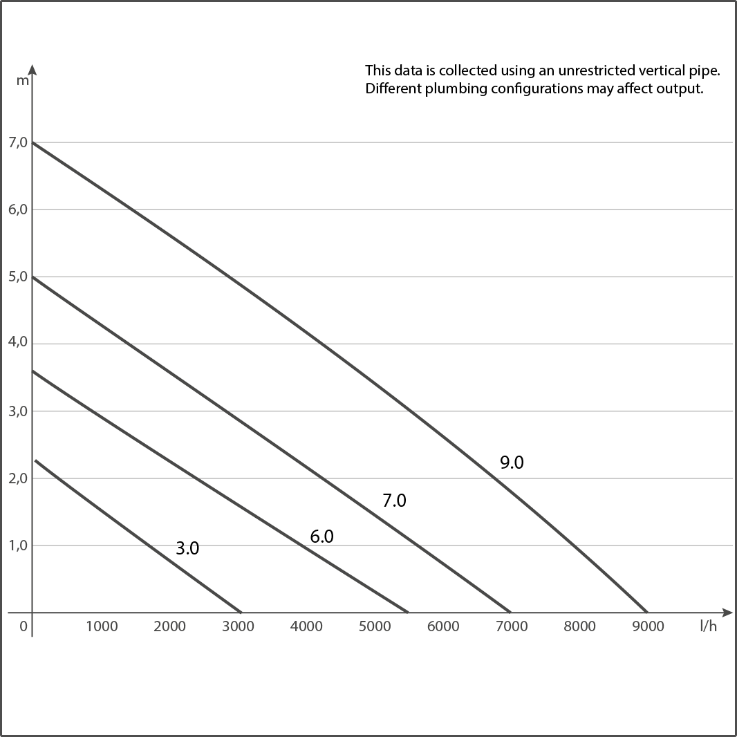
Chart readings are approximate visual estimates from manufacturer graphs, not bench tests. For a selection close to the target, request a clearer curve or tabulated point for the supplied model. A small estimated surplus is not a reliable allowance for an unknown nozzle or partly closed valve.
Reef Octopus VarioS-4: controllable operation and external control
The VarioS-4 has five speed settings, a float-switch input, and a 0–10V input for compatible external control. Its manufacturer specifications list 40 W, 24V DC operation, and a 1-in outlet connection. Choose it when those control options and its actual curve fit your return.
For the 10.2-ft example, the 14.7-ft maximum does not prove usable reserve at 600 GPH. Get the flow at that head before buying, and confirm the supplied union and hose adapters match your plumbing. Also distinguish VarioS-4 from a skimmer pump bearing a similar model name.
Check current price on Amazon →Sicce Syncra SDC 6.0: app control for a suitable head range
The SDC 6.0 provides ContrALL app control, alerts, and submerged or inline operation. Its instruction manual gives a 530–1,450-US-GPH flow range and a 10–40 W power range across settings. Those flow endpoints are not its installed output at every height.
The 6.0 performance curve supports screening a lower-head return such as the 300-GPH-at-5.7-ft example. At 10.2 ft, its remaining flow is below the larger example’s requirement. Wi-Fi features cannot compensate for that shortfall.
AquaIllumination Axis 90: a compact pump to screen for lower head
The Axis 90 has an integrated driver, wireless control, feed mode, and flow-level calibration. Its dimensions and specifications give a width of 2.91 in and height of 7.75 in, useful measurements when planning a crowded return chamber.
Its approximately 10-ft maximum head rules it out for the 10.2-ft example. For a shorter return, obtain the required flow point before choosing it. The “up to 90 gallons” tank-size description and the 925-GPH maximum do not prove that it can deliver your chosen turnover through your pipework.
Check current price on Amazon →Current USA eFlux 1900: check the model 6010 curve
The eFlux 1900 is model 6010. The manufacturer’s flow chart plots it beside models 6008, 6009, and 6011. Follow the line marked 6010. Using the 6011 line would substantially overstate the pump you are comparing.
Its 380–1,900-GPH published adjustment range, LOOP Hub controller, and 1.5-in threaded pump connections make it worth comparing when the installation can use those connections. The roughly 600-GPH curve reading at 10.2 ft is close to the target; at lower head there is more room to tune. Check unions, reducers, and the drain limit before using the upper setting.
Check current price on Amazon →How much reserve should you leave?
Reserve means extra flow available at the head you need, within the pump’s permitted operating range. A much larger zero-head number is not enough. There is no single percentage that covers every unknown fitting, equipment addition, or maintenance condition.
Screen the candidate against the measured route and a reasonable upper estimate for uncertain losses. If a minor change in added head makes the curve miss the target, resolve that uncertainty or choose a pump with more usable capacity. Check the lower end too: an oversized pump that cannot turn down far enough may be awkward to match to a small overflow.
Keep the extra capacity available for adjustment; you do not have to run it continuously. A clean strainer and impeller are still necessary. Spare headroom is not a substitute for removing an obstruction.
Measure the Flow After Installation
Set the sump to its normal working level, use the intended pump setting, and leave the normal equipment branches open. Record the valve positions so that later measurements describe the same setup.
Use an inline sensor within its measuring range
An inline sensor can show changes in installed flow without redirecting the return. The Neptune FS-100 manufacturer information specifies 150–1,500 GPH, an FMM connection for Apex readings, and supplied unions adapting the sensor to standard 1-in PVC. A return below its supported range needs a suitable sensor or another measuring method.
Place a sensor upstream of a manifold only if you want the combined flow. A sensor in the display-return branch answers a different question. To check a UV branch, measure that branch; the main pump’s total is not its UV throughput.
Follow the specific sensor’s instructions for orientation, straight-pipe space, and electrical placement. Put unions and service access around it so cleaning does not require rebuilding the return. Account for its loss rather than assuming a measurement device is hydraulically invisible.
Use a timed container only if you can preserve the return conditions
A timed collection can provide a one-time check when the outlet can be safely accessed. The measurement is useful only if the route, discharge height, restrictions, and pump setting remain representative of normal operation. Running a temporary hose straight into a bucket on the floor usually reduces head and overstates display flow.
- Prepare a clean, marked container large enough for the intended collection and safe to handle. Keep electrical connections dry.
- Arrange collection at the normal discharge height without removing the restrictions you intend to measure. If doing so requires unsafe climbing or pulling on a bulkhead, use an inline sensor instead.
- Start with the sump at its normal level. Prevent automatic top-off from adding fresh water in response to water being temporarily collected.
- Collect a known volume for a measured time. Stop before the container fills or the sump intake approaches its minimum safe submersion.
- Restore the return arrangement, return the collected aquarium water if it remains clean, and restore normal top-off operation. Repeat only after normal water levels have settled.
Convert the result with:
US GPH = collected US gallons × 3600 / collection seconds
L/h = collected liters × 3600 / collection seconds
For example, 2 US gallons collected in 24 seconds would be 300 GPH. This is an illustrative calculation, not a measured pump result. Collecting from one outlet of a split return measures only that outlet. Sum separately measured branches under comparable conditions if you need the total.
Keep a useful baseline
Record the installed pump model, setting, sump level, open branches, and measured flow after commissioning and after cleaning. These details help you distinguish a gradual loss from an intentional change to a valve or device.
| Observation | First check | What the finding tells you |
|---|---|---|
| Flow was adequate, then fell at the same setting | Intake, impeller, sensor, hose kinks, and valve position | A restriction or maintenance issue may explain the change before a larger pump is needed |
| Pump output appears unstable or bubbles enter the display | Return-chamber water level, intake submersion, and air reaching the pump | Address water or air supply before increasing speed |
| Display flow falls when an equipment branch opens | Measure both the branch and the display return | The main pump is sharing flow; a single-line estimate cannot calculate the split |
| Drain noise or surging begins after increasing speed | Reduce to the previous stable setting and check the drain type | The drain or its tuning may be limiting usable return flow |
| Flow is low even with a clean pump and open return | Compare the exact curve with actual pipe measurements | The pump, route, or assumed losses may need to change |
Check the Complete System Before Leaving It Unattended
A pump can meet its flow target while the rest of the system still needs attention. Check leaks, stable water levels, and loss-of-power behavior with the final nozzle positions and plumbing in place.
Keep the pump and fittings serviceable
Allow space to remove the intake screen and impeller assembly. Install unions where the pump, sensor, or a valve needs to come out for cleaning. Support the pipe so that disconnecting a union does not transfer its weight or sideways force to the aquarium bulkhead.
Select bulkheads by the tank-hole diameter, tank thickness, gasket requirements, and slip or threaded connection. The nominal pipe size alone is insufficient. A change to the pump or pipe may require a compatible adapter, but forcing a poorly fitting connector is not a solution.
For an inline pump, follow the manufacturer’s water-supply requirements. The Sicce SDC instructions specify placement below water level because the pump is not self-priming, and require the impeller to stay wet. They also prohibit operation with the outlet fully closed. Apply the actual manual’s limits to your pump rather than assuming every AC or DC design behaves alike.
Treat manifold flow as a separate sizing problem
A manifold lets one pump supply several paths, but opening a branch changes the main pump’s operating flow and the share reaching the display. You cannot represent every branch by adding its flow to the tank-turnover target or by entering its pipe length as though all the water travels through it.
Establish the display-return requirement, each device’s flow requirement, and the branch geometry. For a complex split, use a hydraulic calculation that resolves the branches or measure and balance the completed system. A separate equipment pump can be easier to control when one device needs a narrow flow range independent of display turnover.
Test power-off drainback
Begin at the intended operating sump level, with the return outlets in their final positions. Disable top-off during the test so it cannot alter the water balance. Switch the return pump off and watch water drain into the sump until the levels stop changing.
The sump needs to contain drainback from the display, overflow, and plumbing with spare capacity. If the level approaches the rim or any component’s safe limit, stop the test and correct the operating fill level or drainback arrangement. Do not leave the aquarium unattended on the assumption that a check valve will always seal.
Return outlets placed deeper in the display can allow more water to siphon back. Keep any intended siphon-break opening accessible for inspection and cleaning, and repeat the test after a change to nozzle depth or plumbing.
Test restart and feeding modes separately
Restore power and watch the display, drain, and return chamber. The pump must have water, the drains must return to stable operation, and neither vessel should approach an unsafe level. Be ready to switch the pump off if the display keeps rising or the intake starts drawing air. Restore top-off only once the system is stable.
Check feeding and maintenance modes too. A calibrated low-flow mode that keeps a pump energized does not prove what happens during a true power outage. Make sure the normal setting resumes as intended and that any delayed skimmer restart suits its chamber water level. If the drain will not restart reliably, resolve that with the overflow troubleshooting guide and the overflow’s instructions.
Maintain the baseline instead of chasing the largest reading
Disconnect power before removing pump parts. Clean the intake, impeller, and housing by the method allowed in the pump manual, then measure again at the recorded setting and water level. If flow returns to its adequate baseline, there is no evidence of a pump-capacity shortfall.
Recheck flow and drainback after adding equipment, changing hose, moving a nozzle, or altering valves. A backup pump is useful only if it fits the connections and can provide adequate flow at the installation’s head. Keeping its adapters ready makes replacement more practical than relying on a spare with incompatible fittings.
Frequently Asked Questions
How many GPH should my reef return pump deliver?
Choose a return-turnover target for a stated operating water volume, then check filtration and drain limits. As a first calculation, 75 US gallons at 4× gives 300 GPH. The pump needs to deliver that flow at the calculated return head. Coral circulation within the display is a separate requirement.
Is the calculator’s GPH my actual pump output?
It is the target you set by multiplying volume and turnover. The calculated head tells you where to check a pump curve for that target. Installed output depends on the exact pump, setting, and complete plumbing; measure it after installation.
Can I use liters and meters?
Convert liters to US gallons and meters to feet before entering them, then round to the field steps. The 400-liter example uses 106 US gallons, 4.9 ft of rise, and 16.4 ft of straight pipe. Pipe choice still depends on actual inside diameter and pipe type.
How much head does a 90-degree elbow add?
There is no fixed head loss per elbow. This calculator allows 30 inside diameters of equivalent straight pipe for a 90° elbow and 16 for a 45° elbow. Their head loss depends on flow and diameter; fitting-specific data can give a better estimate for the installed fitting.
Does horizontal pipe length matter?
Yes. It adds friction, and the vertical pipe does too. With 4 ft of vertical pipe and 20 ft of horizontal pipe, enter 24 ft of total straight pipe and 4 ft of rise. There is no universal allowance of one foot of head for every ten feet of horizontal pipe.
Is maximum head a usable operating height?
Maximum head is near the shutoff point, where flow approaches zero. A pump with a 10-ft maximum head cannot be chosen to supply 600 GPH at about 10.2 ft. Use the curve point where the pump can still deliver your required flow.
Should I adjust the DC pump or close a valve?
Use the pump’s permitted speed controls for normal adjustment when available. An accessible return valve can provide isolation or permitted fine tuning, but closing it adds resistance. Follow the pump manual’s minimum-flow limits. Never use an emergency drain as the return system’s flow-control valve.
Can I add a UV sterilizer to the return later?
Only after checking the specific UV unit’s flow requirement, connections, and effect on the circuit. A branch needs its own flow assessment; total return GPH is not the UV’s flow. Recheck display flow after opening the branch, and repeat shutdown and restart checks after the plumbing changes.
Is an adjustable DC pump always the better choice?
Adjustability is useful when tuning flow to an overflow or accommodating uncertain losses. An AC pump can also work when its curve, permitted installation, and control method fit the system. Compare installed flow, access for cleaning, replacement parts, and the features of the exact model; the electrical label alone does not establish noise, efficiency, or suitability.
Final Installation Checklist
Before treating the return system as ready:
- Write down the operating-volume basis and target turnover.
- Measure rise and the full straight-pipe route separately.
- Confirm actual inside diameter and count installed elbows.
- Identify additional losses and keep unknown allowances recognizable.
- Check the exact pump curve at the resulting flow-and-head point.
- Confirm the pump fits, can be serviced, and can adjust to the drain’s usable range.
- Measure installed display-return flow with the normal branches open.
- Check power-off drainback, restart, feeding modes, and normal water levels.
- Record the final setting and flow so future maintenance has a baseline.
Sources and Manufacturer References
- NCEES FE Reference Handbook, printed page 174: Hazen–Williams equation
- Charlotte Pipe: plastics technical and installation manual
- Bulk Reef Supply: return-pump sizing and sump turnover
- Neptune Systems: COR plumbing guidance
- Reef Octopus: VarioS circulation-pump specifications
- Sicce: Syncra SDC performance chart
- Sicce: Syncra SDC instruction manual
- AquaIllumination: Axis specifications and dimensions
- Current USA: eFlux model specifications and flow chart
- Neptune Systems: FMM and FS-100 flow-sensor specifications