

 Published sources
 Product details checked
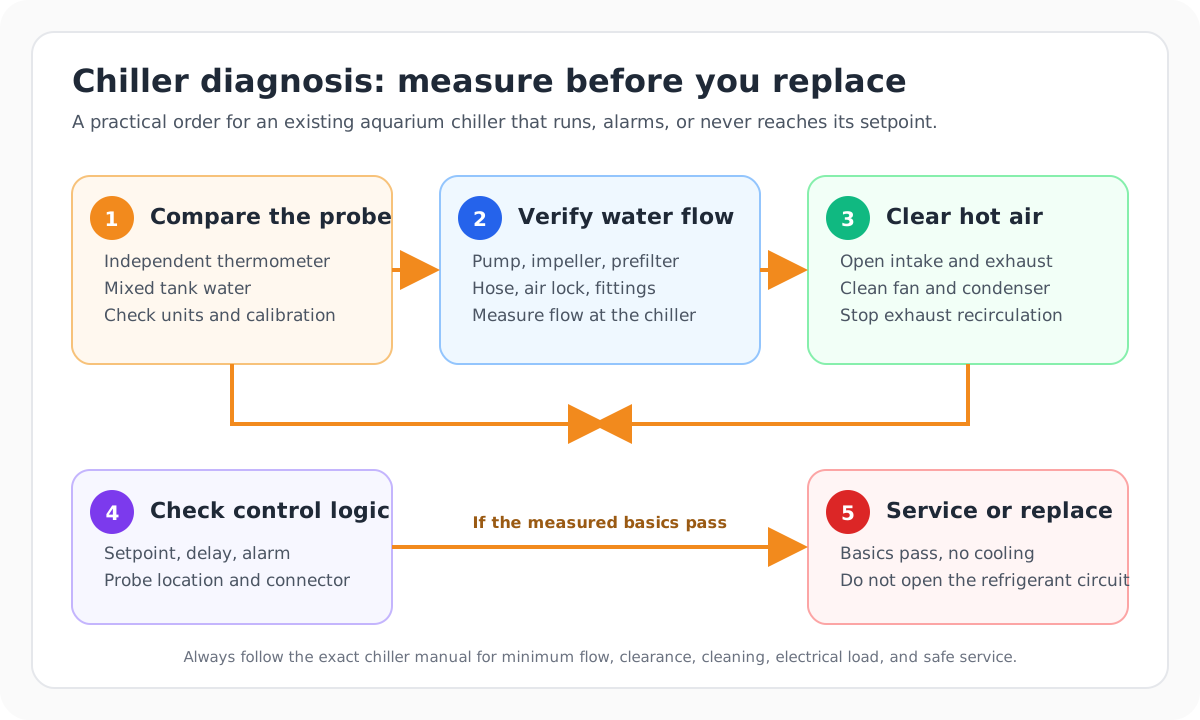
If your aquarium chiller is running without cooling the tank, check the water temperature with a separate thermometer first. Next clear the air intake and exhaust, measure the water actually passing through the chiller, and compare that flow with the exact model’s operating range. Once those checks pass, assess the heat entering the aquarium. A fan noise, a cold hose or a pump’s advertised output cannot establish whether the system is working properly.
A chiller that previously reached the target and suddenly struggles needs a different investigation from one that has never managed the installation. Loss of flow, dust, a displaced probe or changed room conditions can explain the first pattern. The second also calls for a capacity check. Neither pattern proves that the compressor has failed.
Work through the checks below in order, changing one thing at a time. Record what changes in the aquarium water, rather than judging a repair from the chiller display alone. The model examples use published manufacturer specifications; they are not results from our own equipment tests.
Jump to temperature and control, airflow, flow measurement, heat load or service decisions.
Protect the aquarium before troubleshooting
If the water is above the suitable range for your animals, reduce avoidable heat while arranging a controlled response. Dim or switch off unnecessary lighting, shade the aquarium from direct sun, and cool the room if possible. Keep essential filtration and suitable aeration operating. Check that an enabled heater is not adding heat during the cooling problem.
There is no single emergency temperature for every aquarium. Coldwater fish, tropical fish, reef animals and other aquatic inhabitants have different requirements. Merck’s fish-housing guidance explains why species-appropriate temperature, an independent thermometer and protection from direct sunlight matter. Warmer water also holds less oxygen.
If fish are gasping, losing balance or otherwise distressed, seek prompt advice from an aquatic veterinarian and check water quality as well as temperature. Those signs do not identify a chiller fault by themselves. Avoid dumping ice, ice water or a large volume of markedly colder water into the tank. A fast temperature correction can introduce another stressful change.
Stop for an electrical hazard. Do not operate equipment with a damaged cord, water inside electrical parts, smoke or a burning smell. If a plug or outlet is wet, disconnect the circuit safely at the breaker before touching it. Use dry connections and drip loops. Disconnect the chiller and pump before opening plumbing or performing maintenance, following their manuals. Never open the refrigerant circuit, add refrigerant or bypass a safety switch.
The JBJ Arctica owner’s manual covers electrical precautions and requires circulating water and checking for leaks before powering the chiller. After any work on the loop, restore and verify water flow before restarting refrigeration.
Identify what “not cooling” means
Take a moment to separate the symptoms. A lit display shows that some electronics have power. It does not show that the compressor is running. Likewise, a working fan can coexist with a compressor delay, a control fault or insufficient cooling capacity.
| Observation | First useful distinction |
|---|---|
| Display is dark | Check the dry-side power supply and the manual’s permitted power checks; repeated trips need investigation |
| Display says the water is cool, but a separate thermometer reads warm | Compare the sensors in representative water before changing calibration |
| Display reads above target, but cooling does not start | Check the trigger differential, cooling indicator, external controller and restart delay |
| Water flow is weak, intermittent or full of air | Check the complete water circuit before running the compressor further |
| Chiller runs continuously and the tank stays warm | Test airflow, measured flow and heat load in the sequence below |
| Chiller starts and stops repeatedly or shows an alarm | Record the exact model and alarm; use its manual instead of a generic code list |
1. Verify the temperature reading and the cooling call
Compare sensors in the water you want to protect
Put a reliable independent thermometer in well-mixed aquarium water, away from a heater, direct light, a cold chiller return and stagnant corners. Allow it to settle according to its instructions. Record the chiller display and any external-controller reading at the same time.
For a sump installation, also compare the display aquarium with the sump. Poor mixing or a return that draws water straight back into the chiller intake can make one small area reach the setpoint while the aquarium remains warm. The temperature of the main body of water is the result that matters.
Keep the type of sensor in mind:
- An integrated chiller sensor normally measures water within the unit. Its reading can differ from the aquarium if flow is interrupted or long exposed tubing changes the water temperature.
- An external-controller probe measures its installation location. Keep it submerged in representative flow, clear of the heater and chilled return.
- An independent thermometer is a reference only if it is working and used correctly. Resolution to a tenth of a degree does not establish accuracy to a tenth of a degree.
If two movable probes disagree, compare them close together in the same stable water before deciding that placement or calibration is responsible. Do not enter an offset merely to make displays look identical. A damaged sensor, a poor reference thermometer or a real temperature difference needs its own correction.
TECO’s troubleshooting guidance specifically identifies heat gained or lost through long, uninsulated tubing as a cause of a display mismatch. Its sensor-fault instructions are separate from that explanation. A wrong reading does not automatically mean the sensor has failed.
Check whether cooling should have started
Read the current temperature, setpoint and cooling differential in the same unit. The setpoint is the target setting. The differential, sometimes called hysteresis, determines how far the temperature must move before the controller starts or stops cooling. A temperature slightly above target may still be inside the normal control band.
Check the following before changing settings:
- Confirm that °F or °C is selected correctly.
- Confirm that the programmed target is appropriate for the aquarium and below the independently measured water temperature when cooling is needed.
- Look up the model’s cooling indicator and start/stop behavior. A flashing indicator can have a different meaning from a steady one.
- Check whether an external controller is supplying power to the correct cooling outlet.
- Allow the specified compressor-protection delay after a power interruption or a cooling stop.
Do not keep lowering the target to force a start. That can conceal a sensor problem and leave a dangerously low setting once the underlying fault is corrected. Nor should you repeatedly switch the power off and on: each restart may begin another protection delay.
The Active Aqua instructions explain the controller and compressor behavior for the AACH range. Use the manual for your revision rather than applying its button sequence or delay to another brand.
Check an external controller without defeating protection
A second controller can prevent a chiller from receiving power even when the chiller’s own display would otherwise call for cooling. Check its temperature reading, cooling threshold, delay and outlet assignment. If heating and cooling controls overlap, the aquarium may receive heat while the chiller tries to remove it.
The Inkbird ITC-308S specifications include separate heating/cooling control, calibration, alarms and compressor-delay protection. An alarm or switching relay is useful information, but it does not increase the chiller’s capacity.
Use a controller only with compatible electrical equipment. Check the exact regional rating, the chiller’s running and starting requirements, and whether the chiller restarts correctly after switched power. If that compatibility is unclear, ask the manufacturers. Do not bypass the chiller’s internal controls to make a test work.
Move on when: the reference reading is credible, the aquarium really needs cooling, and you understand whether the compressor is running or waiting. Resolve a definite sensor or control error before treating it as a refrigeration problem.
2. Check the air path and the room around the chiller
Follow the intake and exhaust
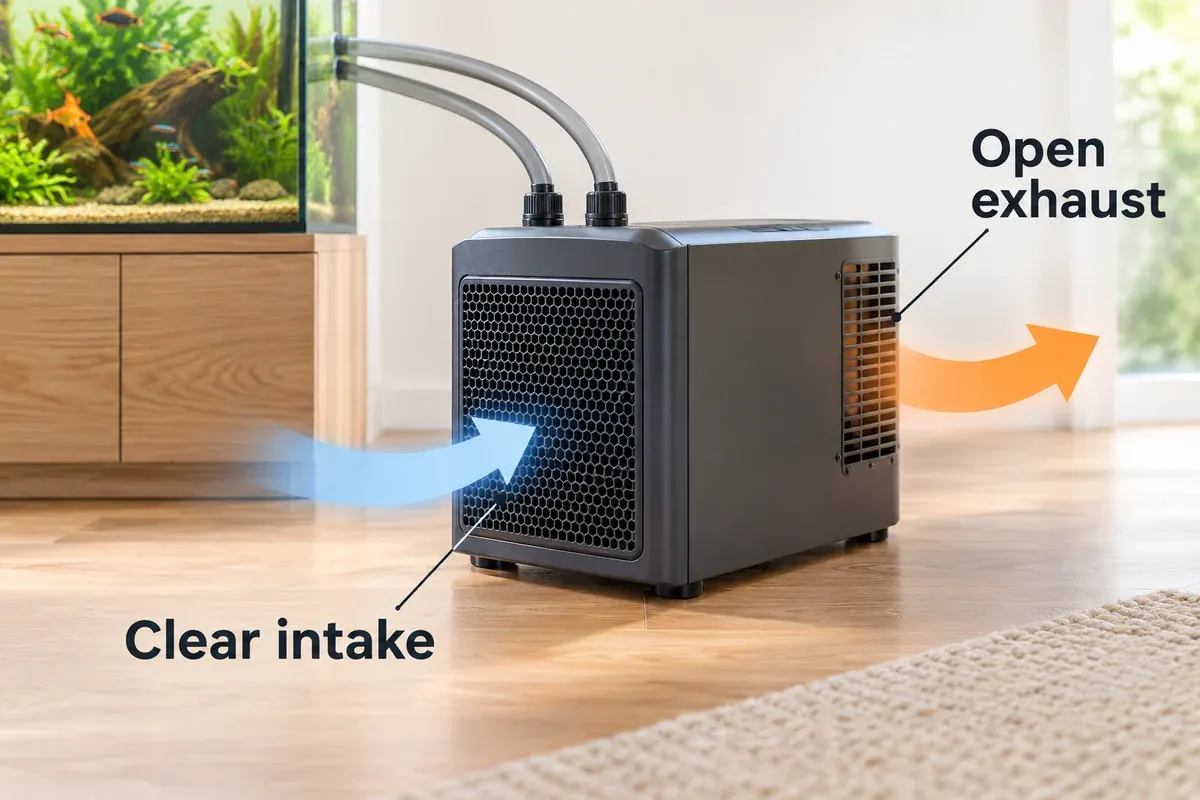
A compressor chiller removes heat from the water and releases it into the surrounding air, together with heat from its own electrical operation. The room must carry that heat away. A chiller inside a sealed stand can keep drawing in its own warm exhaust and lose performance even with a working water pump.
Identify the actual intake and exhaust from the manual. Look for a wall, dust buildup, furniture, a curtain, stored equipment or another appliance obstructing either path. Do not assume that a gap above the case makes the front and rear clear. Check what happens with the aquarium cabinet in its normal operating state, including closed doors.
For the JBJ Arctica Aquarium Series, the manual requires at least one foot (30.5 cm) before the condenser intake and one foot behind the exhaust. It also warns against an enclosed aquarium stand. This clearance belongs to that series; it is not a universal instruction for every aquarium chiller. JBJ installation instructions, printed page 5.
Measure the air temperature close to the intake, keeping the thermometer out of the exhaust stream. Compare it with the room away from the chiller. A comfortable thermostat setting across the room can hide a hot pocket around the unit. Compare the intake conditions with the model’s operating limits and performance conditions.
If cooling improves when an obstruction is removed, plan a permanent installation with the required air path. Leaving a cabinet door open for a short test does not prove the closed installation is adequate.
Check the air space around the unit as well as the water moving through it. A case can fit in a cabinet while the chiller’s operating air paths remain obstructed.
Clean the permitted air-side parts
Disconnect power, let hot parts cool, and follow the manual for the air filter, grille and accessible condenser. Remove dust with the permitted method. Avoid bending delicate fins or forcing dirt farther into the unit. Keep tools and fingers away from fans, and restore required grilles before operation.
Fan movement alone does not establish that enough air crosses a clean condenser. Conversely, a fan that should run but does not is a service issue, rather than a reason to leave a guard removed or try to spin the blades by hand.
TECO lists dirty filters, hot ambient air, obstructed grilles and a failed fan among its air-side fault causes. Its alarm meanings apply to the relevant TECO equipment. Record the code on your own model before consulting its troubleshooting table. TECO troubleshooting.
Move on when: the intake and exhaust remain clear in the normal installation, the permitted cleaning is complete, and ambient conditions are within the model’s requirements. If these changes restore cooling, retain the chiller and correct the installation.
3. Measure the water going through the chiller
Trace the complete circuit
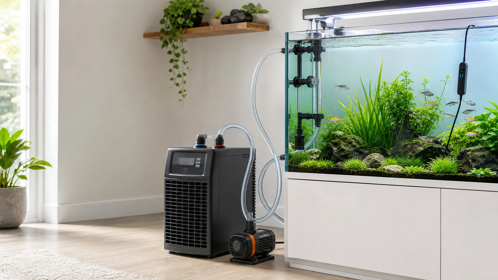
Follow the tubing from the intake to the return. Identify the pump, prefilter or canister, chiller, valves, any branch and the actual return outlet. The manufacturer’s installation diagram determines the order and connections; a diagram for another model does not establish compatibility.
A common arrangement is:
aquarium or sump
  → approved pump/filter
  → chiller inlet
  → chiller outlet
  → aquarium or sump
The water moving around the aquarium is not necessarily the water moving through the chiller. In a shared return, a branch may supply most of the display flow while very little reaches the cooler. Measure the chiller branch after its restrictions, not the combined pump output before the split.
Check for partially closed valves, kinked tubing, blocked strainers, incorrect inlet/outlet connections and trapped air. Check that fittings are seated and unused installation plugs have been removed. A pump that hums or vibrates can still be delivering too little water.
With power isolated, inspect the impeller, impeller well and intake according to the pump or filter instructions. Keep a submersible intake below water and an external pump properly primed. Restart only after the loop is filled, connections are secure and leaks have been checked. Never run the chiller without the required water circulation.
Keep filtration while removing the restriction
Inspect mechanical media, the prefilter and tubing for accumulated debris. Restore the intended media arrangement rather than stripping out all filtration to produce a higher number. Biological media should be handled according to the filter manual, and essential filtration needs to continue during longer service work.
The Fluval 07 Series manual documents maintenance of the intake, hoses and impeller as well as the media. Its warning against replacing all media at once matters when a cooling problem tempts you to empty the canister.
If you use a canister, our guide to a canister filter that will not prime covers the air and startup checks. Once circulation returns, measure the flow again. A visually stronger return is useful progress, but it is not yet a measured operating rate.
Fluval 307: pump output and filter circulation are different figures
For the Fluval 307, the manufacturer’s specification table gives:
| Published specification | Flow (US GPH / L/h) |
|---|---|
| Pump performance | 303 US GPH / 1,150 L/h |
| Filter circulation | 206 US GPH / 780 L/h |
Source: Fluval 07 Series manual, English specification table EN-3. The table also describes its hose measurement condition. These are published ratings, not a measurement of your installed chiller circuit.
780 L/h is approximately 206 US GPH. The pump and circulation figures must stay attached to their respective labels. Adding a chiller, other fittings, different hose runs or fouled media changes the hydraulic resistance. Neither number establishes the flow through the completed installation.
Use these conversions for your own measurements:
US GPH = L/h ÷ 3.785411784
L/h = US GPH × 3.785411784
Manufacturer pairs can be rounded differently: 1,150 L/h converts to about 303.8 US GPH, while Fluval publishes 303 US GPH for pump performance. Keep the original labeled specifications when reporting the manufacturer figure; use a consistent conversion when calculating a measured result. An Imperial gallon is a different volume, so an unlabeled “gallon” bucket needs checking. NIST’s volume-conversion table lists US and Imperial gallons separately.
Compare with the exact chiller’s limits
Two chillers with the same HP label can require different flows:
| Chiller model | Published water-flow range |
|---|---|
| Active Aqua AACH10HP | 132–396 US GPH / 500–1,500 L/h |
| JBJ Arctica DBA-075 | 240–960 US GPH / approximately 908.5–3,634 L/h |
Sources: Active Aqua AACH10HP instructions, specification page 3 and JBJ Arctica manual, printed page 7.
Active Aqua publishes the rounded US GPH and L/h pair shown above. The JBJ L/h values are calculated from its US GPH limits and rounded. Use the original US GPH limits when a measurement is close to either boundary.
The Fluval 307’s 206 US GPH filter-circulation rating is below the DBA-075’s 240 US GPH minimum. Its higher pump-performance figure does not prove that the installed filter/chiller loop meets that minimum. With the AACH10HP, the published circulation figure falls between the flow limits, but additional resistance can still take the actual result below the required range. In either case, confirm that the equipment and plumbing arrangement are permitted and measure the completed loop.
Do not turn every pump to maximum. Excess flow can exceed a chiller’s permitted range or pressure limit. Nor should you reduce flow below the minimum because the outlet “feels colder.” Work within the specified range and judge the aquarium’s temperature trend.
A bucket test that preserves the useful measurement
Use a timed collection only if you can secure the outlet and control the water without opening live equipment, flooding the floor or exposing an intake. If the plumbing cannot be tested safely that way, use a suitable installed flow meter or ask for help with the circuit.
- Turn the chiller’s refrigeration off. Isolate the pump before changing the outlet arrangement.
- Use a clean, accurately marked container large enough for the test. Know whether its scale is liters or US gallons.
- Keep the outlet near its normal return elevation and retain the same tubing and restrictions as far as practical. Lowering a free outlet to the floor or removing a restrictive return changes the test conditions.
- Secure the outlet, confirm enough water remains above the intake, and run the primed pump at its normal setting.
- Once the stream is steady, collect a measured volume and time the collection. Stop before the receiving container overfills or the intake can draw air.
- Repeat under the same conditions. Restore the outlet, refill or return suitable water as needed, check for leaks and confirm circulation before restarting cooling.
flow in L/h = liters collected × 3,600 ÷ seconds
flow in US GPH = US gallons collected × 3,600 ÷ seconds
Worked metric example: 2 liters collected in 10 seconds gives 720 L/h, or approximately 190 US GPH. That result is inside the AACH10HP’s published range and below the DBA-075’s minimum. It is an example calculation, not a measured recommendation for every installation.
Worked US example: 5 US gallons in 30 seconds gives 600 US GPH, or approximately 2,271 L/h. That exceeds the AACH10HP’s maximum, although it falls inside the DBA-075’s range. A bucket test supplies a number; the model manual determines what the number means.
A free-outlet test is still an approximation if the return’s normal backpressure cannot be reproduced. Record that limitation. If repeated readings vary or sit close to a limit, improve the measurement rather than treating the most favorable result as proof of suitability.
Move on when: flow is steady, free of unintended air, and demonstrably within the exact chiller’s required range under representative operating conditions. If it is below range, identify the restriction or unsuitable pump before investigating cooling capacity.
4. Distinguish poor flow from excess heat load
Read flow and temperature together
With credible temperature readings, open airflow and suitable measured water flow, observe a normal cooling run. Keep the pump setting, lighting schedule and other relevant conditions recorded. Allow for the compressor delay and for sensors to respond; there is no universal number of minutes that proves a chiller has failed.
If safe, reliable measurement points are already available, compare water entering and leaving the chiller during sustained operation. Do not dismantle plumbing or install improvised probes just to obtain a temperature difference. Check the sensors together first: a small apparent difference may be no larger than their measurement uncertainty.
A cooler outlet shows that heat is being removed at that moment when the measurement is trustworthy. It does not establish the full rated cooling capacity. At a higher flow, the temperature change on each pass can be small while a substantial amount of water is cooled. A large change across a weak trickle can also coexist with inadequate cooling of the whole aquarium. Feeling a hose is insufficient to distinguish those cases.
| Measured pattern | What to do next |
|---|---|
| Flow is below the model minimum, whatever the outlet temperature | Restore an acceptable water circuit before judging the refrigeration |
| Flow is in range; the tank cools after the air path is corrected | Keep the chiller and resolve its permanent ventilation |
| Flow and airflow are acceptable; the outlet is measurably cooler, but the tank stalls above target | Investigate heat entering the system and whether cooling performance matches the installation |
| Cooling improves when an avoidable heat source is reduced, with flow unchanged | That heat source contributes to the problem; assess the required permanent load |
| A sustained cooling call produces no trustworthy cooling trend after the basic checks | Arrange a manufacturer or qualified-service diagnosis; the remaining fault is not identified by the display alone |
Multiple problems can occur together. Clearing a filter does not prove the condenser is clean, and a change in the light schedule does not prove the chiller is delivering its specified capacity.
Check what changed in the aquarium or room
Review the conditions when the system last held its target. Useful questions include:
- Has summer weather, a closed room or another appliance raised the temperature beside the intake?
- Were more lights, longer lighting hours or direct sunlight introduced?
- Has a heater stayed energized during a cooling call, or is its setpoint above the intended cooling target?
- Were pumps, a larger sump, extra equipment or a lower temperature target added?
- Was the chiller moved, enclosed or connected with longer tubing?
- Did performance deteriorate gradually between maintenance visits or immediately after plumbing work?
Reduce one avoidable heat source at a time while maintaining essential water movement and animal care. Repeat observations under comparable conditions. A daytime result with lights off does not establish that the aquarium will remain stable at peak room temperature with its normal equipment running.
For a heater adding unwanted heat, our aquarium heater placement guide explains representative probe positions and why extra heaters do not prevent a stuck-on failure. A heater that keeps adding heat needs correction; increasing chiller size is a poor substitute for fixing that fault.
Separate cooling the water once from holding the target
Pulling warm water down to the target removes stored heat from the system. Maintaining that target requires removing the continuing heat entering from equipment and surroundings. A longer pull-down allowance can spread the first task over more time, but it cannot eliminate the ongoing load.
Tank volume therefore has different implications from room temperature or equipment heat. More water takes longer to change temperature at the same net cooling rate. A warmer room can both add heat to the aquarium and make heat rejection harder at the condenser. A smaller aquarium in difficult conditions can exceed a chiller’s usable capacity despite fitting a nominal tank-volume label.
Use the aquarium chiller size calculator to organize water volume, temperatures, equipment heat and pull-down assumptions for capacity planning. Confirm the selection against the manufacturer’s performance data or sizing advice for those conditions. The calculator is a planning aid, not a diagnostic test of an existing compressor.
For example, Hydrofarm’s AACH10HP instructions include performance curves under stated ambient and starting-water conditions. Those curves are not a guaranteed aquarium cooling time at a different target temperature. Similarly, JBJ qualifies its aquarium-capacity label by equipment and the required pull-down. A compressor HP label alone cannot tell you whether either model will hold your particular system.
Move on when: you can describe the actual heat load and operating conditions, and the chiller still shows unexplained loss of performance or fails to maintain the target. A unit that never met the target needs a sizing discussion as well as fault checks; one that lost performance under unchanged conditions needs service investigation after maintenance and installation faults have been excluded.
5. Know when the next step is service
Stop using the unit and obtain help for damaged electrical parts, a burning smell, repeated protective trips, abnormal compressor noise or a leak that could affect electrical equipment. If a model reports a persistent sensor or fan fault, follow its service instructions. Do not assume that an alarm can be cleared safely by repeated resets.
When measurement, ventilation, water flow and load have been checked but cooling remains inadequate, the possibilities include sensor/control problems, a fan fault, heat-exchanger fouling or a refrigeration fault. A warm tank does not identify which component failed. Refrigerant leaks may have no obvious smell, so smell is not a reliable test of circuit condition.
Keep air-side cleaning and water-side cleaning separate
Dust on condenser fins affects the air path. Deposits inside the water heat exchanger affect a different part of the system. The permitted cleaning procedure can depend on materials, deposits and the model.
Do not pour a cleaner into the aquarium or copy a descaling concentration from a different brand. If the manufacturer permits water-side cleaning, isolate the chiller from livestock, follow its specified fluid and circulation procedure, and flush as instructed before reconnecting. If the instructions are missing or the procedure requires inaccessible parts, ask the manufacturer.
The JBJ manual describes an isolated clean-water heat-exchanger flush as part of its maintenance instructions. TECO publishes a different procedure for calcium buildup. These are reasons to use the applicable instructions, not interchangeable recipes. A persistent performance problem after permitted maintenance still needs diagnosis.
Give service a useful record
Before contacting support, collect the model, serial number, voltage, purchase information and exact alarm text. Add photos of the installation taken from a dry, safe position. The record should show where air enters and leaves and how water passes through the loop.
Include the independent water temperature, chiller display, controller settings, intake-area temperature, measured flow with its test conditions, and changes already tried. Note whether the compressor appeared to run, whether the fan behaved normally and whether cooling once worked in this same installation. This allows support to distinguish an installation mismatch from a component fault without guessing from “it runs but stays warm.”
Do not remove covers to obtain internal electrical readings, refrigerant pressure or a compressor diagnosis. Have electrical and refrigeration work performed by appropriately qualified service personnel.
Keep a measurement log while troubleshooting
Make one record before a change and another after it, using the checklist below for each observation. Keep the units consistent and include elapsed time. Mark a reading “not measured” rather than filling it from a pump label. You can copy this table into a notebook or spreadsheet.
| Record | Entry for this observation |
|---|---|
| Time and observation period | Record the time and elapsed minutes |
| Independent aquarium temperature and unit | Record the reference reading |
| Chiller display, target and differential | Record all three values |
| External-controller reading, outlet state and delay | Record if fitted |
| Air temperature beside the intake | Record the local air reading |
| Flow, collection volume/time and outlet arrangement | Enter the measured rate and test conditions; remeasure if changed |
| Lights, heaters and essential equipment running | List what is operating |
| Fan, compressor indicator and alarms | Record observations and exact alarm text |
| Single change made | Write “baseline” before changes; otherwise describe the one change |
Record the temperature trend as well as the final reading. If the room cooled during an airflow test or lighting changed during a pump test, include that difference. Otherwise you can attribute an improvement to the wrong repair.
Repair, reconfigure or replace?
The measurements should lead to a specific next step:
- Flow returns after permitted cleaning: retain the chiller, record the restored rate and maintain the restricting component.
- The installed loop cannot meet the flow range: assess the pump curve, branches, tubing and approved equipment arrangement. Replace or reconfigure the component responsible for the gap.
- Cooling returns with a clear air path: make that ventilation permanent and retest under normal peak conditions.
- Measurement or control is wrong: correct or service the relevant sensor/controller before evaluating cooling capacity.
- Load exceeds a correctly operating system: reduce avoidable heat or plan a suitably rated installation with manufacturer support.
- Basics pass and performance remains inadequate: obtain a service assessment, then compare supported repair with replacement.
A dirty filter does not automatically need a new canister, and a failed chiller does not automatically need a larger compressor. Check support, parts, warranty conditions and compatibility before ordering a replacement. Keep the existing biological filtration operating during any longer change of equipment.
Replacement chillers: two model examples with different constraints
If diagnosis supports replacement, the Active Aqua AACH10HP is a 1/10 HP example with a titanium evaporator and the lower flow range shown above. Match its fittings, electrical version, flow and performance conditions to the aquarium. An installation that exceeds its maximum flow or cannot reject exhaust heat is unsuitable even if the tank falls within the nominal volume guidance. Hydrofarm AACH10HP specification.
Check current price on Amazon →The JBJ Arctica DBA-075 is another 1/10 HP example, with a higher minimum flow. It needs an installation meeting its own water and air requirements. A Fluval 307 pump label by itself is insufficient evidence of that fit. Ask for sizing advice if the old unit never maintained the target in the intended room. JBJ Arctica specification and manual.
Check current price on Amazon →Frequently asked questions
Why is the chiller fan running while the water stays warm?
The fan can run without useful compressor cooling. Check the cooling call and restart delay, then air conditions, measured water flow and load. Fan noise establishes neither refrigerant-circuit health nor adequate heat rejection.
Is 780 L/h enough for an aquarium chiller?
It depends on the exact model and the actual installed flow. 780 L/h is about 206 US GPH. That falls within the AACH10HP’s stated range and below the DBA-075’s 240 US GPH minimum. If 780 L/h comes from a Fluval 307 specification, it is a filter-circulation rating, not your measured result after adding the chiller.
Will slowing the pump make the chiller cool better?
Do not take it below the manufacturer’s minimum. A colder outlet stream at reduced flow can be misleading when less water is passing through. Adjust only within the permitted operating range and evaluate the aquarium temperature, with airflow and load held comparable.
Why does the chiller cool at night but struggle during the day?
Compare intake-area temperature, lighting, sunlight and equipment operation across those periods. Daytime heat can exceed the capacity available in those conditions. Confirm the measured flow and maintenance before assuming the solution is a larger unit.
How long should I wait to see a temperature drop?
Follow the model’s restart delay and use an observation period long enough to resolve a trend with your thermometer. Water volume, starting temperature, ongoing heat, available cooling and sensor response all affect the result. A fixed waiting time cannot diagnose every system.
Can I install the chiller inside an aquarium stand?
Use the model’s installation instructions. The cited JBJ Arctica manual warns against enclosed stands and requires a clear intake and exhaust. A grille or cabinet fan does not automatically establish an approved installation or adequate air exchange.
Should I recalibrate the display if it disagrees with the tank thermometer?
First confirm the reference thermometer, placement, water circulation and units. Long tubing or a sensor close to the chilled return can produce a real difference. Calibrate only as instructed after those causes have been checked; replace or service a faulty sensor rather than hiding its error with an offset.
Can a controller repair the cooling problem?
A compatible controller can provide alarms and switching. It cannot clear a restriction, restore airflow, repair refrigeration or supply missing capacity. Its own thresholds and delays can also explain why the chiller has not started.
Should I buy a stronger pump or a bigger chiller first?
Measure flow first. If it is below the model’s range, resolve the water circuit. If flow and airflow meet requirements but the aquarium remains warm, assess heat load and cooling performance with the manufacturer. Choose equipment for the demonstrated limitation.
Once a repair appears successful, repeat the check with the aquarium’s normal lighting, equipment and expected warm-room conditions. Keep the flow measurement and temperature log as a baseline for future maintenance.
Sources and further reading
- Fluval 07 Series user manual, English table EN-3: separate 307 pump-performance and filter-circulation ratings, measurement note and filter maintenance.
- NIST Guide to the SI, Appendix B.8: US and Imperial volume conversions.
- JBJ Arctica Aquarium Series manual, printed pages 2, 5–7: electrical precautions, air clearance, startup, calibration, maintenance and model flow limits.
- Active Aqua AACH instructions: AACH10HP flow range, performance conditions, installation and controller behavior. Match the instructions to the unit’s revision.
- Hydrofarm AACH10HP specification and JBJ Aquarium Series specification: model construction and selection details.
- TECO troubleshooting: model-family examples of air-side faults, display differences, sensor faults and water-side deposits.
- Inkbird ITC-308S specifications: control differentials, compressor delay, calibration, alarms and electrical limits; use the correct probe and regional version.
- Merck Veterinary Manual: providing a home for fish: species-appropriate temperature, independent monitoring, sunlight and the temperature/oxygen relationship.